
Last Updated on March 16, 2024
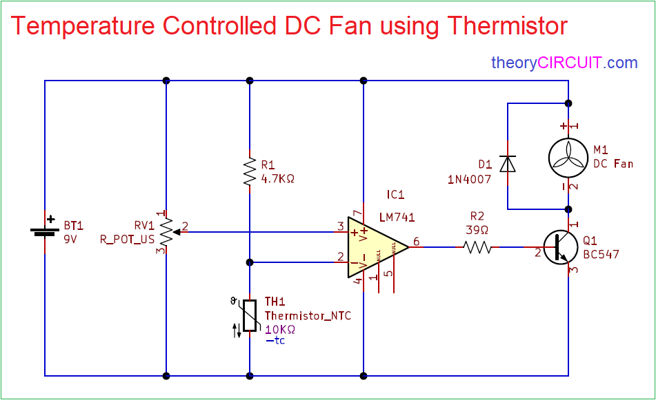
Simple Temperature Controlled DC Fan Circuit is designed with Negative temperature co-efficient Thermistor and an operational amplifier. This Thermistor variable Resistance value based on the temperature, When the temperature rises then Thermistor Resistance gets decrease and for temperature decrease then Thermistor Resistance gets Increase. We can choose threshold point of temperature by using variable resistor.
We can implement this Temperature Controlled DC Fan circuit in a common PCB and place the Thermistor sensor near the place where temperature controlling is need.
Circuit Diagram
Components Required
- Thermistor NTC 10KΩ
- Operational Amplifier IC LM741
- DC Fan 9V
- Transistor BC547 NPN
- Resistors 4.7KΩ, 39Ω each one
- Variable Resistor 10KΩ
- Diode 1N4007
- Battery 9V
Construction & Working
Here Operational Amplifier compares Reference voltage at non inverting input and inverting input and controls output voltage by using op-amp output transistor BC547 acts as switch to connect or disconnect DC fan from power supply.
Variable Resistor VR1 is connected across power supply and variable pin is connected to the Non inverting input of IC 741 and then NTC thermistor is connected between the power supply through R1 Resistor and also connected with Inverting Input of IC 741. Operational amplifier also uses the same power supply source and output is connected to the Q1 transistor base through R2 Resistor. 9V DC fan is conned with positive supply and Q1 transistor collector terminal, here the Q1 transistor acts as switch. When the temperature increase and reaches the threshold then op-amp gives differential voltage and makes Q1 transistor turn ON then DC fan gets ground supply and starts to run. If the temperature level below the threshold then op-amp gives zero output then Q1 transistor stays in turn OFF condition and DC fan don’t get bias to run and so it remains in off condition.
Thermistor
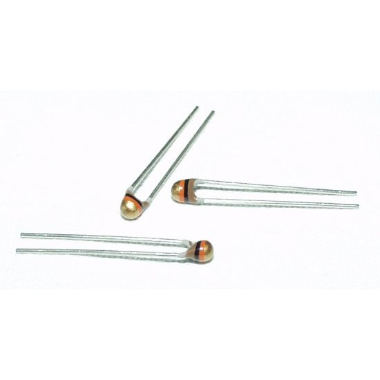
This Thermistor element don’t have polarities and we can connect the terminals in any direction.
Transistor BC547
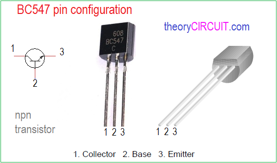
Transistor BC547 is a Three terminal two junction active device (NPN), we can configure BC547 pin as facing the flat surface and pin 1 is called as Collector terminal and 2 is Base and Pin 3 is called as Emitter terminal. It can be used in general purpose, amplification and switching applications.