
Last Updated on April 20, 2024
We know the Oscillator is a electronic circuit which produce sinusoidal or non sinusoidal wave with required frequency and amplitude. Every Oscillator circuits will have tank, amplifier and feed back circuit to produce waveforms. Here RC phase shift Oscillator circuit designed to produce sinusoidal wave form with few easily available components.
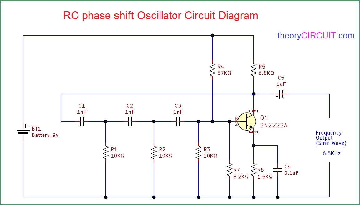
Simple RC Phase shift Oscillator Circuit to oscillate pure Sine wave up to 6.5KHz. Output signal frequency is depends on the tank circuit elements and its value, here the tank circuit consist with Resistors and Capacitors.
RC phase shift Oscillator Circuit Diagram
Components Required
- Battery 9V
- Transistor 2N2222A (NPN)
- Resistors 10KΩ = 3
- Resistor 57KΩ, 6.8KΩ, 1.5KΩ, 8.2KΩ each one
- Capacitors 1nF = 3
- Capacitor 0.1μF, 1μF each one
Circuit Construction & Operation
Here Transistor 2N2222A biased as Common emitter (CE) single stage amplifier and at the feed back RC network is formed by same value capacitors and Resistors. Output is picked up from Transistor collector terminal through output coupling capacitor C5. This whole RC phase shift oscillator circuit is powered by 9V battery.
When we apply the power supply to this circuit, the random variations of base current caused by noise variations in the transistor and voltage variations in the power source produce oscillation, and this variations amplified by the transistor amplifier.
RC Phase Shift Oscillator Output Frequency Formula

Where:
Fr is the Output frequency in Hertz,
R is the Resistance in ohms (R= R1 = R2 = R3),
C is the Capacitance in Farads (C = C1 = C2 = C3),
N is the Number of RC stages (here N = 3),
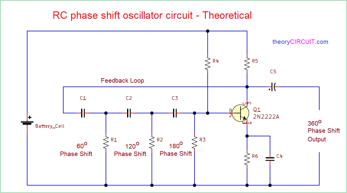
This RC phase shift oscillator feedback network is consists of three stages of RC networks and these are identical and has equal values. Here each RC combinations provides 60º phase shift to the signal (RC1 + RC2 + RC3) that is (60 + 60 + 60) totally feedback section provides 180º phase shift. The amplifier stage provides amplification with 180º phase shift. Hence the total phase shift is 360º, and it provides positive feedback and hence continuous undamped Oscillation is produced. We can obtain continuous sine wave output with fixed frequency. RC phase shift oscillator circuit will provide stable low frequency oscillation.
Circuit is not biased correctly. Remove R7 completely and change R4, R5 and R6 all to 10k. My Tina simulation oscillated at 9.4kHz
I have built this circuit with value changes in my previlous reply. It worked with supply voltages from 4V to 12v. Approx 10kHz oscillation.
Could anyone please tell me:
If i want to build this circuit and want it to give me 0 (or near 0) – 1800 Hz,
(higher is OK, but not necessary)
-Where should i put the potentiometer(s)?
-How many Ohms should the potentiometer(s) have?
-What other transistors can i use? -what hFE? -what happends if i use a higher or lower hFE?
To Barry Moore (or anyone else who have built this circuit):
-How does it’s output look in an oscilloscope?
-How many Volts is it’s output?
-What happends if i keep R7 and the other values? -does it still works?
(just curios)
Thank you very much! /M
Hi M
Refer this article for more information. (https://resources.system-analysis.cadence.com/blog/msa2020-rc-phase-shift-oscillator-design-for-sine-wave-generation)
The circuit does not work in the way described in the article.
Hi Colin,
Thanks for pointing this out. You’re right — a few readers (including Barry Moore in the comments below) have already flagged that the circuit as published doesn’t bias correctly with the listed values.
A couple of clarifications on the theory too: the “60° per RC stage” explanation in the article is a simplification — in a real cascaded RC network the stages load each other, so the phase isn’t split evenly, even though the total still needs to hit 180°. Also, hitting the phase condition alone isn’t enough — the amplifier also needs a gain of at least 29 to satisfy the full Barkhausen criterion (magnitude + phase), which wasn’t called out explicitly here.
That, combined with the bias network (R4=57k, R5=6.8k, R6=1.5k, R7=8.2k) not putting the transistor at the right operating point, is why several readers reported the circuit not oscillating as described.
If you want a version that actually works: set R4 = R5 = R6 = 10kΩ and remove R7 entirely — this was verified in simulation and on the bench by Barry Moore, oscillating around 9–10kHz (higher than the 6.5kHz ideal-formula value, since the transistor’s input impedance loads the last RC stage and shifts the real frequency up). Appreciate you flagging it.