
Last Updated on March 16, 2024
IR beam from remote control travels very short distance with narrow angle so that here we given IR remote control extender circuit with few components.
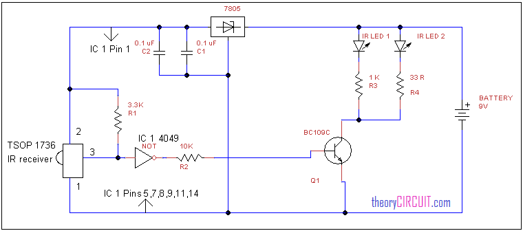
Circuit diagram
Construction and Working
The IR receiver TSOP 1736 is used to detect the IR beam from remote control, output form this sensor is fed to not gate and inverted output is connected to transistor Q1 base, this NPN transistor acts as switch and the IR LEDs connected with this transistor creates IR beam as received.
This isn’t going to work because the TSOP17xx module is a receiver and demodulator which only receives IR modulated on a carrier (36KHz for TSOP1736) and outputs the demodulated data signal _without,_ the carrier.
So this circuit will only receive signals from remote controls which use a 36KHz carrier but rebroadcasts them as carrier-free data signals which will not operate the targeted consumer equipment because it is designed to receive the carrier signal and reject anything else as interference.