
Last Updated on May 9, 2024
FS1000A 433MHz RF transmitter and receiver Brief Note For wireless application design. This 433MHz Tx and Rx module uses ASK (Amplitude Shift Keying) Modulation. These modules are used in multiple applications like, For Short distance communication, Home Automation, Remote controls and Car security etc.., Many manufacturers producing these TX RX modules with frequency range from 315MHz to 334MHz. Especially Wenshing from Taiwan Makes (303.875MHz / 310MHz / 315MHz / 318MHz / 418MHz / 433.92MHz) Wireless ASK RF Transmitter and Receiver. Due to its simple operation and shape, these modules are widely used in many wireless applications. By understanding its operation and internal schematic you can also explore the ability of ASK RF Transmitter and Receiver.
Before jump into the Hardware and Schematic operations, let us recall What is ASK? and How it is Work? We know Amplitude Shift Keying is the part of Digital Modulation Techniques. Here input is Digital data either logic HIGH (1) or logic LOW (0) and the Carrier is sinusoidal wave with 433MHz (frequency varies with respect to Tx Rx Module). Depends on the Digital unipolar binary sequence transistor switch Allows and Stops the Carrier sinusoidal wave. At the output it is appeared as Amplitude shift keyed wave. Due to its frequency range and antenna circuitry it becomes RF wave and propagates.
ASK Waveform
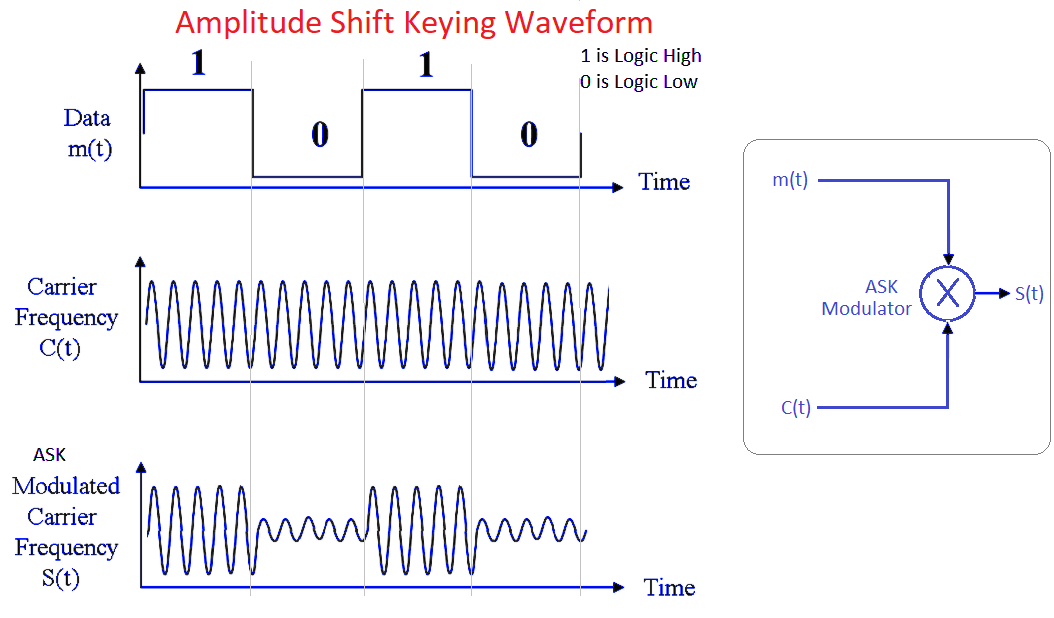
As you can see how the ASK wave S(t) is modulated by using the Digital Data m(t), Carrier Frequency C(t). Depends on the ASK modulator Switch, data modulation (bit rate) varies.
FS1000A 433MHz Transmitter Circuit Diagram
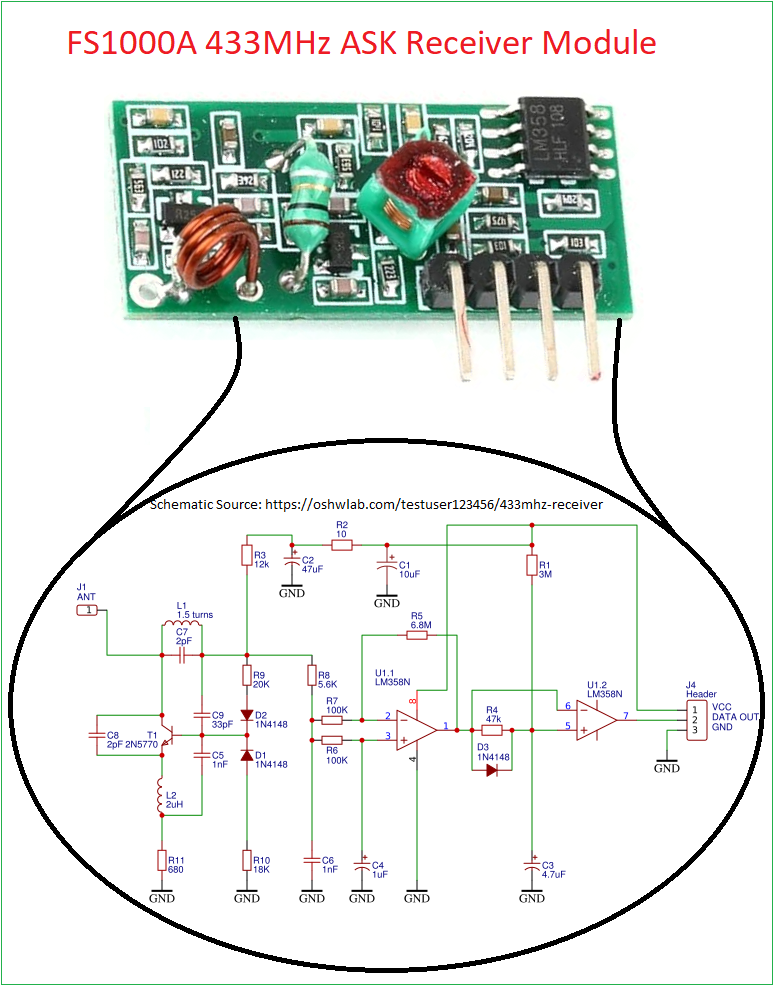
FS1000A 433MHz Receiver Circuit Diagram
Construction & Working
The Transmitter uses 433MHz Crystal oscillator to produce Carrier signal and Transistor Q1 S8050 acts as modulator switch and modulates Digital input data with Carrier signal and converts it into ASK Wave.(SWG18) 8 Turns and 3 Turns coil produce electromagnet wave that can be propagate using Antenna. The schematic inside given for reference and not exact replication of Module. Here the module picture uses 433.92MHz Saw Resonator with to-39 Case.
The 433MHz Receiver Module Contains the following circuits, 1. Rectifier, 2. Envelope Detector, 3. Comparator and 4. Output Buffer.
After Receiving the ASK RF signal, it is amplified by the transistor T1 and Rectified by using two 1N4148 Diodes. Then the Comparator by using LM358 Compares and separates Enveloped signal then it is converted into Square wave (binary sequence) as Data output.
FS1000A 433MHz RF transmitter and receiver Pinout
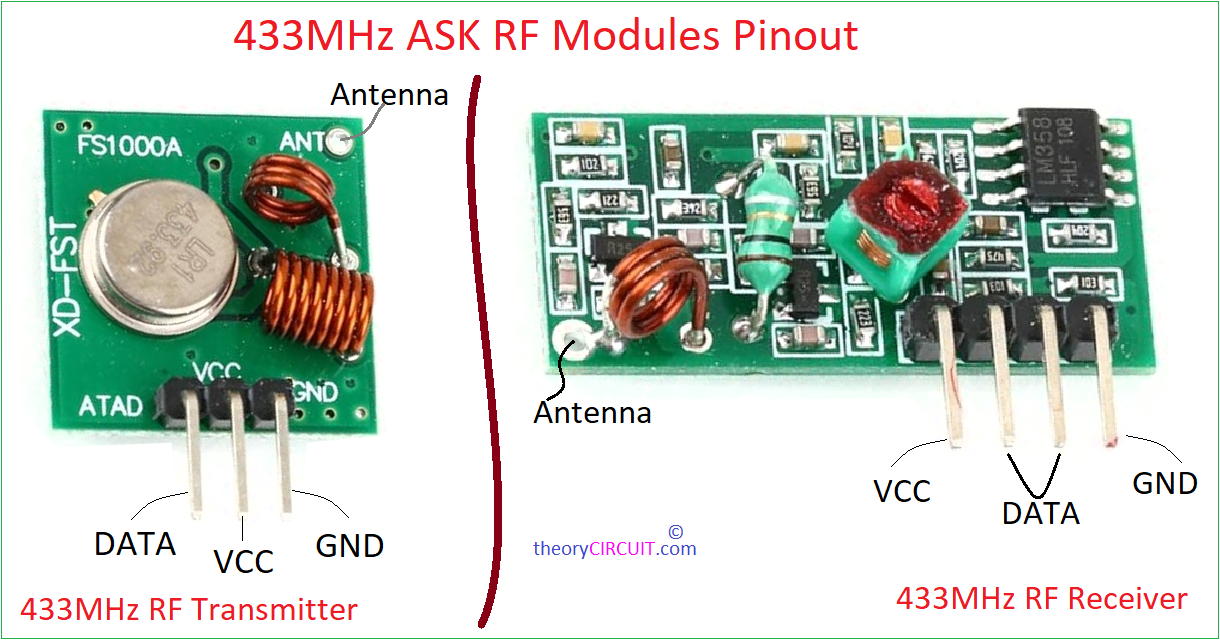
Even though there is no specific pin number, There is a silkscreen Text denoting each pin Name. If there is no such text keep the component on the module toward you face and follow the table for pin details.
433MHz RF TX
| Pin Number | Pin Name | Pin Description |
| 1 | DATA | Data Input pin (Data to be Transmitted) |
| 2 | VCC | +Ve Power supply to the Transmitter circuit |
| 3 | GND | Gnd Supply to the Transmitter circuit |
| 4 (PCB Via) | Antenna | Antenna pin and to be connected with Wire antenna |
433MHZ RF RX
| Pin Number | Pin Name | Pin Description |
| 1 | VCC | +Ve Power supply to the Receiver circuit |
| 2 | DATA | Data Output Pin (Data Receiving Pin) |
| 3 | DATA | Data Output Pin (Data Receiving Pin) |
| 4 | GND | Gnd Supply to the Receiver Circuit |
| 5 (PCB Via) | Antenna | Antenna pin and to be connected with Wire antenna |
Specifications
For Receiver Module
- It can operate with 3V to 9V input DC Voltage.
- Operating Frequency is 433.92MHz (433MHz)
- Transmitter consumes 4mA to 40mA current during its operation.
- It can Transmit up to 100 Meter distance.
- It has 10Kbps Data Transmission rate.
For Receiver Module
- It can operate with 3.5V to 12V input DC voltage.
- Operating Frequency can be minor tuned 433.92MHz (433MHz)
- Current consumption for operation 20mA – 30mA.
- Data Transfer rate 10Kbps.
- sensitivity of this receiver is 105db.
Interfacing
These modules can be used as Wireless Switch, Discrete logic data Transmitter and Receiver or by using HT12E Encoder and HT12D Decoder IC we can interface these modules with Arduino, Raspberry pi or any other micro controllers.
Very good work about the matter. But I think both transistors of the transmitter circuit should be NPN type. Thanks
That comes in a breakout board. Manual assembly may require type of transistor.