Last Updated on March 16, 2024
Simple and Most widely used H-Bridge Motor driver circuit by using L293D plotted in schematic and PCB here, We know an H-Bridge is a circuit which switches polarity of a voltage applied to the load (here load is a motor), Hence we can change the rotating direction of motor.
Here H-Bridge Motor driver coordinates supply and signal to the load motor and drives it accordingly. IC L293D from Texas instruments is a quadruple high current half-H driver. The L293D is capable of providing bidirectional drive currents up to 600mA at voltages from 4.5V to 36V. This IC can drive inductive loads such as motors, Relays, Solenoids, and bipolar stepper motors.
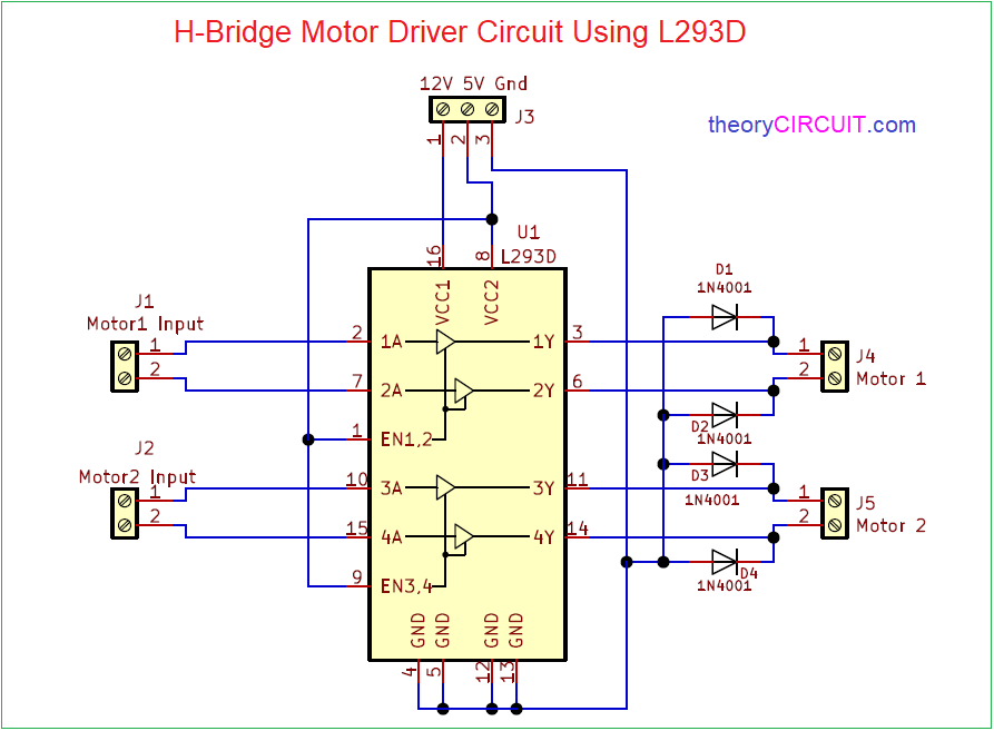
Circuit Diagram
Components Required (BOM)
| 1 | D1, D2, D3, D4 | 1N4001 | D_DO-41_SOD81_P10.16mm_Horizontal | 4 | ||
| 2 | U1 | L293D | DIP-16_W7.62mm | 1 | ||
| 3 | J1, J2, J4, J5 | Screw_Terminal_01x02 | TerminalBlock_Altech_AK300-2_P5.00mm | 4 | ||
| 4 | J3 | Screw_Terminal_01x03 | TerminalBlock_Altech_AK300-3_P5.00mm | 1 |
Construction & Working
This IC L293D comes in 16 pin PDIP package. It has Internal ESD protection, High noise immunity inputs and wide supply voltage range 4.5V to 36V. This H Bridge motor driver circuit using L293D schematic and PCB designs are very simple and it has only four diodes as external components.
This Motor driver circuit designed to drive two separate motors using two inputs. Motor 1 input signal is applied to 1A, 2A pins of L293D and Motor 1 output is taken from 1Y, 2Y Pins. Motor 2 input signal is applied to 3A, 4A pins of L293D and motor 2 output is taken from 3Y, 4Y pins. Here D1 – D4 Diodes are used as Reverse voltage protection form motors.
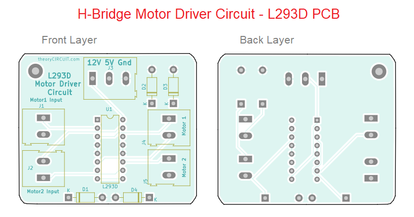
Printed Circuit Board
H-Bridge Motor Driver Circuit using L293D PCB Gerber Files.
Interactive Board Viewer

