
Last Updated on March 16, 2024
A simple 555 Timer Stepper Motor Controller Circuit is designed with few easily available components. This circuit makes stepper motor to drive continuously without any interruption or step stop. By using this circuit we can drive unipolar stepper motors with different voltage ratings. Keep in mind that this circuit uses only 9V power supply and capable of drive stepper motors under 12V. If you want to drive higher than 12V stepper motors then add external power source to stepper motor and power switching transistors.
This circuit has two sections, one is used to generate square pulse oscillation and another one is for provide stepping pulse to the stepper motor.
Stepper Motor
We know stepper motor is also called as stepping motor and mostly it is a brush less DC electric motor and that divides its full rotation into a number equal steps, this motor can be used in different applications like 3D printers, CNC machines, automatic doors etc..,
This stepper motor is basically divided into two categories based on its stator winding,
Bipolar Stepper motor
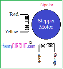
The bipolar stepper motor has single winding per phase and only 4 leads to connect two set of internal electromagnet coils, forward and reverse steps can be achieved by changing the direction of current through the motor coils, this might more complicated than unipolar but the H-bridge and stepper motor driver circuits makes it very simple.
Unipolar Stepper motor
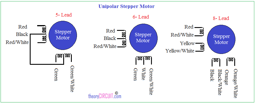
The unipolar comes with 5, 6 and 8 leads and operates one winding with the center tap per phase of input. this image shows different types of unipolar stepper motor and its leads configuration, refer datasheet of your stepper motor to know more.
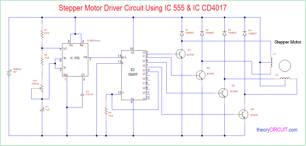
Circuit Diagram
Construction & Working
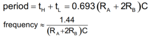
Here the timer IC 555 works as a astable multivibrator and oscillates square pulse based on timing resistor and timing capacitor.
The second stage is decade counter IC CD4017 stage and this integrated circuit counts the square pulses from timer IC and provides stepping pulse output through Q0, Q1, Q2, and Q3 output pins, each pulses are fed into stepper motor coil through switching transistors BC547.
When the pulse and power supply applied to the stepper motor then its rotor starts to rotate, and the speed of rotor can be varied by VR1 Resistor.