Last Updated on March 16, 2024
The servo motors are used in many applications, this motor works with input pulse and rotation depends on input pulse duration. Here the rotation of variable resistor imitate by the rotation of servo motor.(A servo is a rotary actuator)
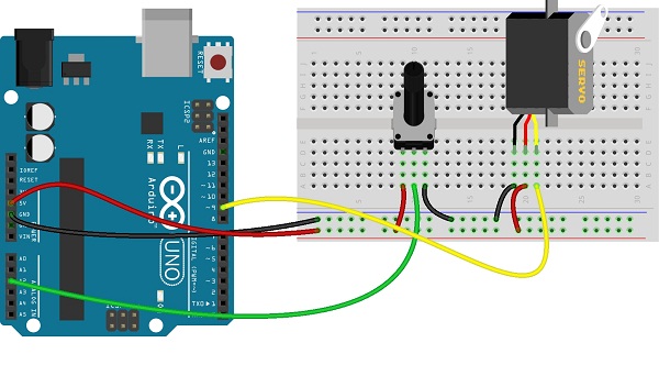
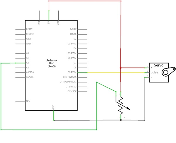
In this project variable resistor connected with analog input pin A0 and the servo motor pulse pin connected with digital pin D9, this pin can give pwm pulse.
Range of variable resistor is converted into digital value and the corresponding pulse width modulation (PWM) pulse is given to servo motor through digital pin D9. Hence we can get rotation from servo motor while we vary resistor value.

Circuit diagram

Analog Input to servo arduino sketch code
[code]
#include <Servo.h>
Servo myservo;
int potpin = 0;
int val;
void setup()
{
myservo.attach(9);
}
void loop()
{
val = analogRead(potpin);
val = map(val, 0, 1023, 0, 180);
myservo.write(val);
delay(15);
}
[/code]
Components List
| S.No | Name | Quantity |
| 1. | Arduino uno | 1 |
| 2. | Variable resistor | 1 |
| 3. | servo motor | 1 |
| 4. | Connecting wires | as required |

What kind of a Variable resistor is it ? Does it have to some value ? so that I can ask for it in hardware stores .
It is normal variable resistor(or) trimpot