Last Updated on March 16, 2024
Even if you are using circuit powered by DC Supply there might be a chance for Overvoltage, Microcontrollers, Microprocessors or sensors might get damage by overvoltage. Here is simple DC Overvoltage Protection Circuit with Relay to avoid such situations. Previously Overvoltage protection circuit designed by using Zener diode and transistor. That circuit acts as regulator and cutoff switch for low voltage DC supply.
This circuit uses SPDT Relay to control DC voltage load with respect to protecting from Overvoltage. (You can transform this circuit to control high voltage DC or AC load with respect J1 – Input DC supply). As we know there are many protection circuits to avoid short circuit, reverse polarity, Over voltage or Current Spike. For high voltage AC / DC supply Fuse and MCBs are used to protect load. The following circuit gives Overvoltage protection for 5V to 32V DC supply powered circuit.
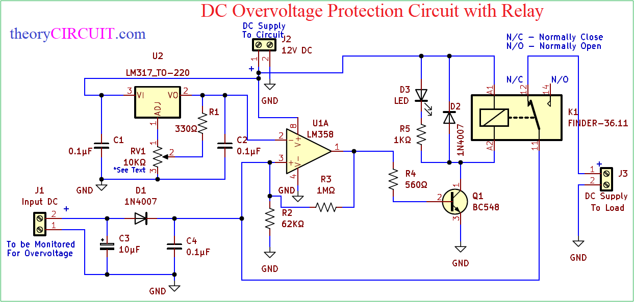
Circuit Diagram
Components Required
| 1 | C1, C2, C4 | 0.1μF | C_Disc_D3.0mm_W1.6mm_P2.50mm | 3 | ||
| 2 | C3 | 10μF | CP_Radial_D5.0mm_P2.00mm | 1 | ||
| 3 | R1 | 330Ω | R_Axial_DIN0207_L6.3mm_D2.5mm_P10.16mm_Horizontal | 1 | ||
| 4 | R2 | 62KΩ | R_Axial_DIN0207_L6.3mm_D2.5mm_P10.16mm_Horizontal | 1 | ||
| 5 | R3 | 1MΩ | R_Axial_DIN0207_L6.3mm_D2.5mm_P10.16mm_Horizontal | 1 | ||
| 6 | R4 | 560Ω | R_Axial_DIN0207_L6.3mm_D2.5mm_P10.16mm_Horizontal | 1 | ||
| 7 | R5 | 1KΩ | R_Axial_DIN0207_L6.3mm_D2.5mm_P10.16mm_Horizontal | 1 | ||
| 8 | D1, D2 | 1N4007 | D_DO-41_SOD81_P10.16mm_Horizontal | 2 | ||
| 9 | D3 | LED | LED_D5.0mm | 1 | ||
| 10 | U1 | LM358 | DIP-8_W7.62mm_LongPads | 1 | ||
| 11 | U2 | LM317_TO-220 | TO-220-3_Vertical | 1 | ||
| 12 | K1 | FINDER-36.11 | Relay_SPDT_Finder_36.11 | 1 | ||
| 13 | Q1 | BC548 | TO-92 | 1 | ||
| 14 | RV1 | 10KΩ | Potentiometer_Alps_RK09K_Single_Horizontal | 1 | ||
| 15 | J1 | Input DC | TerminalBlock_Altech_AK300-2_P5.00mm | 1 | ||
| 16 | J2 | 12V DC | TerminalBlock_Altech_AK300-2_P5.00mm | 1 | ||
| 17 | J3 | DC Supply To Load | TerminalBlock_Altech_AK300-2_P5.00mm | 1 |
Construction & Working
This circuit constructed in Three stages they are 1. Input Stage, 2. Comparator Stage, 3. Relay Switch Stage. For Input Reference, IC LM317 Adjustable voltage Regulator is used. Variable Resistor RV1 position decides the reference voltage to the Comparator. Output Voltage of LM317 can be calculated as Vout = 1.25 {1 + (RV1 / R1)}, Here you can measure the potentiometer resistor value by multimeter or output voltage from the LM317.
This voltage will be the reference voltage for Comparator LM358, Input DC Voltage beyond this level triggers the Comparator to give output voltage and that will turn on Transistor Q1. When the transistor gets turn ON Relay will get Gnd supply and gets turned ON by the way Normally closed switch gets open and load will be disconnected from the Input DC Supply. Change resistor value R2 and R3 feed back to the LM358 depends on your need. Tune the Voltage Regulator for the proper voltage reference input before implementing this circuit to the load.
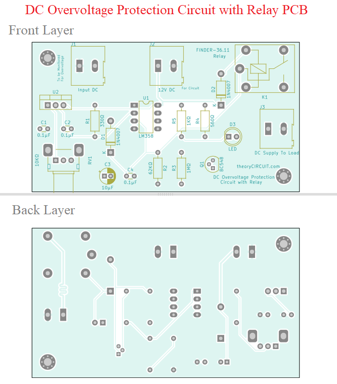
Printed Circuit Board
DC Overvoltage Protection Circuit with Relay PCB Gerber Files.
Interactive Board Viewer


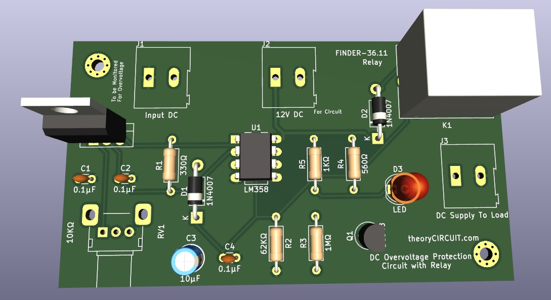
PCB 3D View