
Last Updated on May 6, 2024
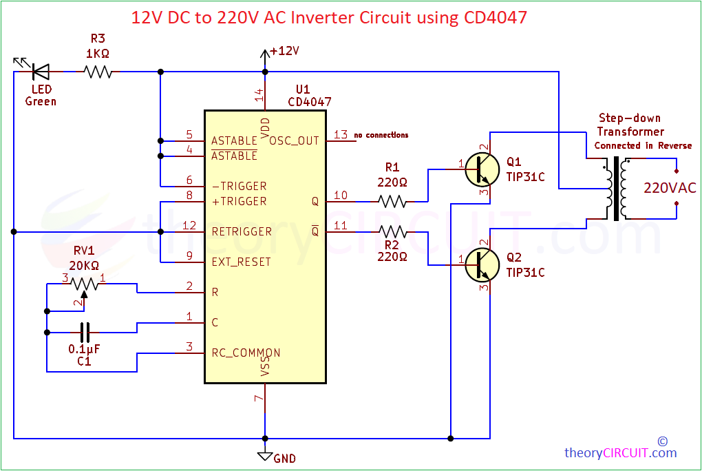
Inverter Circuit converts Direct Current (DC) supply into Alternating Current (AC) supply. It uses switching device like Transistors, MOSFETs or IGBTs along with Transformer and rapidly switch the DC supply ON and OFF so that transformer coil will produce varying magnetic flux and this will cut the other side windings in transformer and makes High Voltage AC through electromagnetic induction. Here 12V DC to 220V AC Inverter Circuit using CD4047 CMOS low power multivibrator IC designed with few easily available external components. It can be used as Power Backup, Emergency power supply with rechargeable battery, or Solar power systems, etc..,
You can understand the typical Inverter circuit operation with the following illustration, As you can see the transformer in the inverter circuit should have less primary winding and Higher number of Secondary winding.

An normal step down transformer can be used in reverse (Secondary as input side and Primary as output side) for low power applications. In order to achieve high efficiency we need to use dedicated Inverter Transformer with right specifications.
Inverter Circuit Diagram
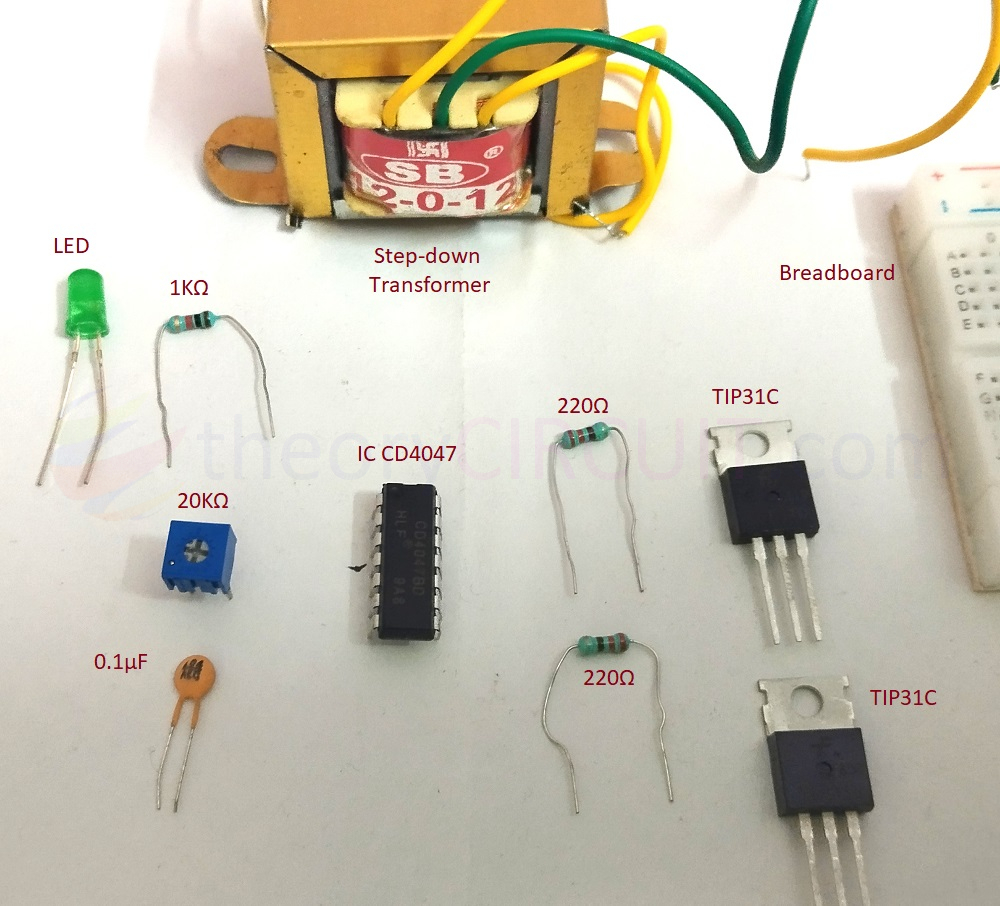
Components Required
- IC CD4047 = 1
- 12-0-12V AC Step Down Transformer 1 Amps
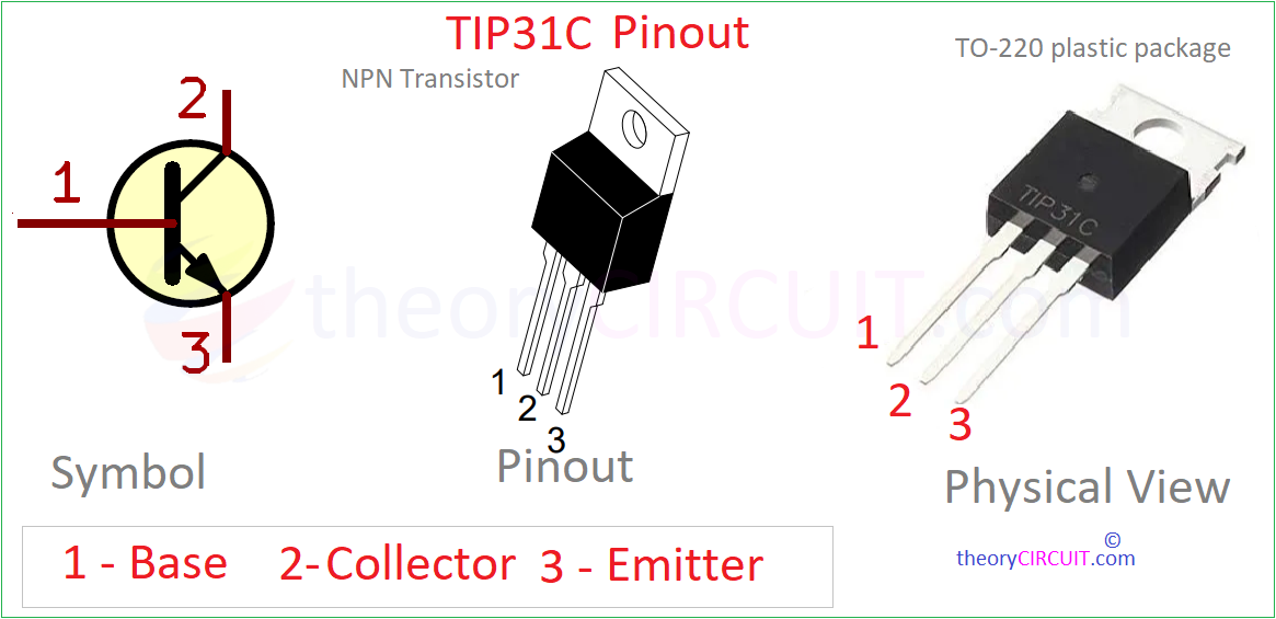
- Power Transistor TIP31C NPN = 2
- Resistor 220Ω = 2
- Variable Resistor 20KΩ = 1
- Resistor 1KΩ = 1
- LED 5mm Green = 1
- Capacitor 0.1μF = 1
Working Video
Construction & Working
This Simple Inverter Circuit is designed to achieve 200Vac to 230Vac output to drive low watt electrical appliance like bulb, tube light, or fan during the power failure or emergency situations.
Here we have used 230V AC to 12-0-12V AC stepdown transformer (center tap) and connected it in reverse. Power transistor TIP31C NPN is used as a switching device, this NPN power transistor comes in TO-220 Plastic package and handles 100V between collector to emitter (VCE) terminals. Having ability of, collector current Ic = 3A and Base Current IB = 1A.
Next main part in this inverter circuit is switching frequency oscillator. CD4047 IC employed here to oscillate continuous square pulse in Q and Qbar Pins. Depends on the timing components RV1 and C1, by varying the trimpot RV1 we can adjust the oscillating frequency and so the output AC voltage from the transformer.
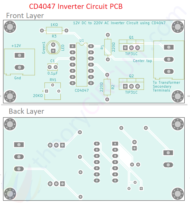
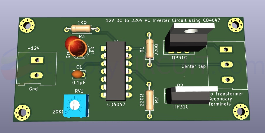
Printed Circuit Board
Download 12V DC to 220V AC Inverter Circuit using CD4047 PCB Gerber File. Here.
Interactive Board Viewer


PCB View
Breadboard prototype
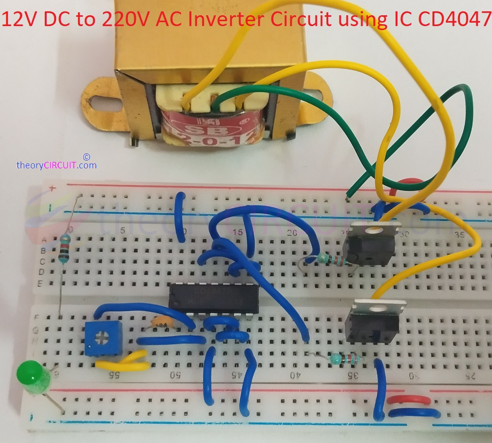
This circuit output is High AC voltage and it is lethal so handle with extreme care and protection.