
Last Updated on April 11, 2025
To detect or measure AC Voltage using Microcontrollers or Arduino is a tough job but the AC Voltage sensor module ZMPT101B makes it very easy and affordable. It is suitable for AC mains voltage measurement and Realtime monitoring, with combination of current sensor, it can be used as a complete power monitoring and control system more than that we can use this sensor module to interface with different microcontrollers.
ZMPT101B
ZMPT101B is a single phase AC Voltage sensor module, it gives precise measurement of AC supply up to 250V and 50Hz/60Hz frequency, main element in this module is a miniature voltage transformer with a 2mA:2mA current ratio. Secondary stage after this transformer have operational amplifier LM358 and multiturn 100KΩ (3296) Trimpot for output Signal Amplitude Calibration. Output signal from this module will be 0-5V depends on the AC supply. Output signal is adjustable through trimpot, so that we can obtain 3.3V or 5V limited output.
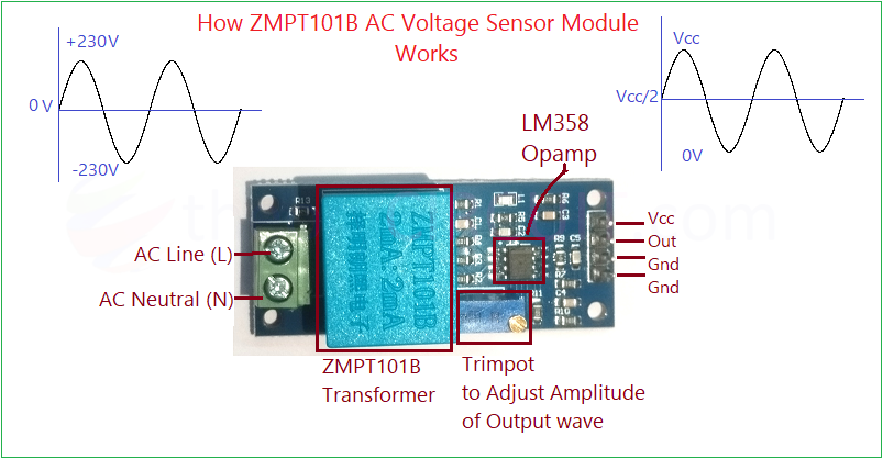
In ZMPT101B AC Voltage Sensor module, miniature transformer steps down the input AC voltage and producing a proportional low current signal. Operational amplifier (LM358) circuit amplifies this signal and gives as output. Depends on the VCC applied to this two stage amplifier and can be adjusted by trimpot.
Here the output voltage is linearly proportional to the input AC supply so that it requires calibration using a known voltage source (You can use multimeter to measure the AC supply for calibration in code) method for calculating calibration factor given near the code. By this way you can measure accurate RMS reading.
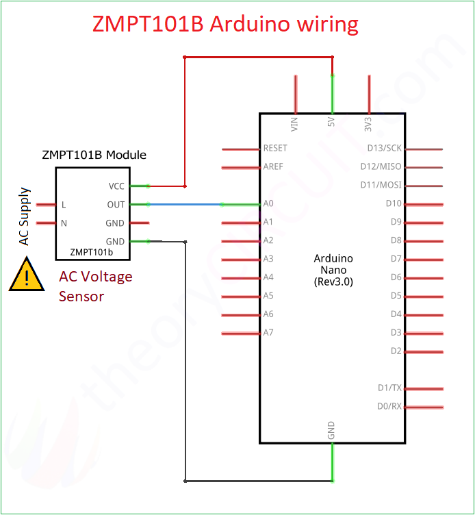
ZMPT101B Arduino Wiring
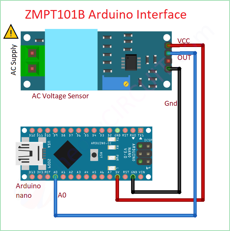
⚠️ This Circuit Involves in Handling of High AC Voltage which lethal, Handle with extreme care.
Video
Construction & Working
Connect ZMPT101B module with Arduino board (here we used Arduino nano) based on the silkscreen text of sensor module, Just Vcc to 5V, Out to A0 pin of Arduino (Analog pin) and then Gnd to Gnd. Now its time to measure and draw the signal. ZMPT101B measures AC voltage and gives an analog signal. Arduino reads it via ADC and calculates voltage.
Code to Plot ZMPT101B module signal
const int sensorPin = A0;
int analogValue;
void setup() {
Serial.begin(9600);
pinMode(sensorPin, INPUT);
Serial.println("Plotting ZMPT101B waveform...");
}
void loop() {
analogValue = analogRead(sensorPin);
// Convert to voltage (for 5V Arduino ADC)
float voltage = (analogValue * 5.0) / 1023.0;
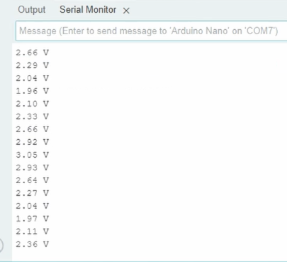
// Print the voltage for plotting
Serial.print(voltage, 2); // 2 decimal places
Serial.println(" V");
// Small delay to stabilize sampling
delay(500); // Adjust for smoother/faster waveform
}
Tune trimpot to get desired minimum and maximum output signal voltage, If you are using microcontrollers like ESP32 then tune it to maximum 3.3V, if your microcontroller reads 5V, then just check the DC offset which is VCC/2.
To get the Accurate AC Voltage readings, Arduino code written as to,
- Initializes analog pin A0 to read voltage from the ZMPT101B AC voltage sensor.
- In the loop, takes 1000 analog samples and centers them around 0 (midpoint = 512).
- Squares each centered value and accumulates the sum for RMS calculation.
- Calculates the mean of squared values and then the RMS using square root.
- Multiplies RMS value by a calibration factor to get actual AC voltage.
- Displays the measured voltage in volts on the Serial Monitor every second.
// ZMPT101B AC Voltage Measurement
const int sensorPin = A0; // Analog pin connected to ZMPT101B output
const int sampleCount = 1000; // Number of samples for RMS calculation
float calibrationFactor = 0.45; // Adjust this value to match real voltage
void setup() {
Serial.begin(9600);
analogReference(DEFAULT); // Uses 5V as reference on Arduino Uno
delay(1000);
}
void loop() {
long sumOfSquares = 0;
for (int i = 0; i < sampleCount; i++) {
int raw = analogRead(sensorPin); // Read raw ADC value (0 to 1023)
int centered = raw - 512; // Center around 0 (assuming VCC/2 baseline)
sumOfSquares += (long)(centered * centered);
delayMicroseconds(100); // Sampling delay (~10kHz sample rate)
}
// Calculate RMS value
float mean = sumOfSquares / (float)sampleCount;
float rms = sqrt(mean);
// Convert to actual AC voltage using calibration factor
float voltage = rms * calibrationFactor;
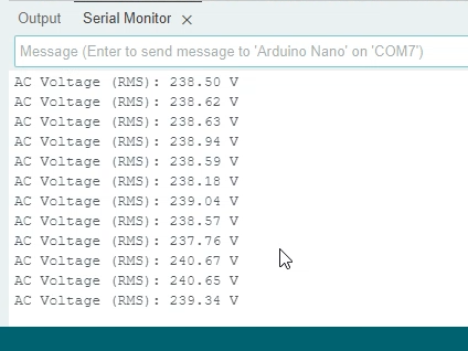
Serial.print("AC Voltage (RMS): ");
Serial.print(voltage);
Serial.println(" V");
delay(1000); // Update every second
}
calculating calibration factor
New calibrationFactor = 0.45 * (Multimeter Value / Serial Monitor Value)
for an example,
If your Arduino IDE Serial Monitor shows 30V but your multimeter shows 230V then –> New calibrationFactor = 0.45 * (230 / 30) ~ 3.45.
Hi, if i wanted to build something similar but the difference is 3 Phase, and the frequency expected range from 320 to 480 hz.
is it possible ?