
Last Updated on March 30, 2024
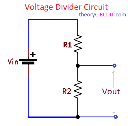
A basic Voltage Divider Circuit made with two Resistors called R1 and R2 by connected in series. where the output voltage (Vout) is taken from the connection point between the two Resistors. Voltage Divider circuits are used to take higher input voltage (Vin) and to convert it into lower output voltage.
Voltage Divider Calculator
Resistor Voltage Divider Circuit
Formula to Calculate Output Voltage.
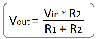
Where,
- Vin is the input voltage applied across the entire circuit.
- R1 and R2 are Resistors connected in series.
- Vout is the output voltage taken from the connection point between R1 and R2.
A Voltage Divider circuit is very useful to reduce the input voltage to a desired voltage level. Output voltage of this circuit is depends on the load Resistor and tolerance of R1 and R2. Check the Vout before employing it in a project.
Applications of Voltage Divider
- Volume Control
- Voltage Level Shifting
- Biasing
- Power supply division
- Sensor interfacing
- Signal Conditioning