Last Updated on March 16, 2024
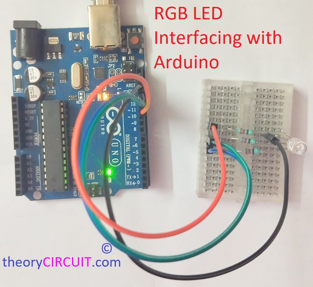
LEDs are revolutionary invention in the history of mankind. It is projected that by 2030 around 87 percentage of all light sources will be LEDs. We use LEDs because of its Vibrant Color Range, Fast switching response, Low power consumption and long life span. Here is a Simple RGB LED Interfacing with Arduino project to learn controlling LEDs with Arduino code.
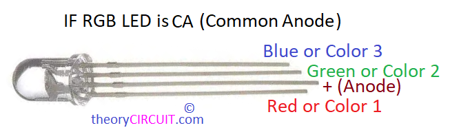
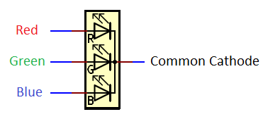
Red, Green, Blue (Primary Colors) LEDs are encapsulated in a single package is called as RGB LED. There are two types of RGB LEDs available in the market. 1. Common Cathode and 2. Common Anode. This is classified by the common pin of all three LEDs inside the package. It requires minimum forward Voltage between 2V to 3.3V.
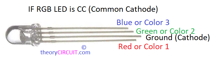
The Common pins in the ‘through hole RGB LED’ will be lengthier than other terminals and you have to refer datasheet for SMD RGB LEDs.
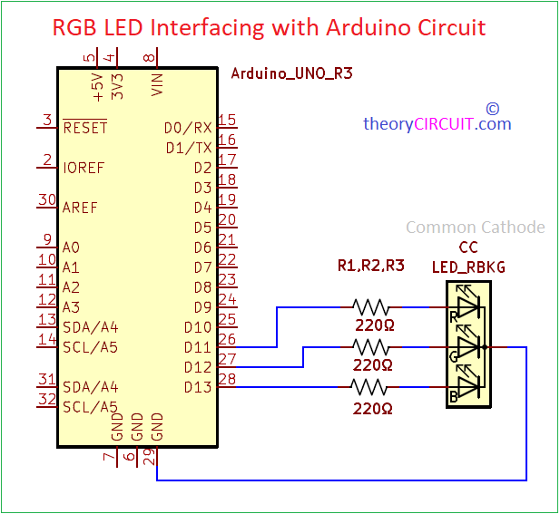
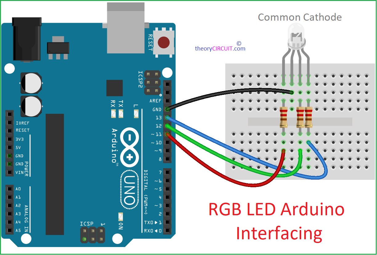
Circuit Diagram
Working Video
Components List
- RGB LED (here Common Cathode)
- Arduino UNO board
- Resistor 220Ω = 3
- Breadboard
- Jumper Wires (Male to Male)
Construction & Working
Before Jump into the wiring lets under stand the RGB LEDs pin configuration. As previously said there are two types of RGB LEDs available, Common Cathode or Common Negative and Common Anode or Common Positive. We have to connect this component in proper forward bias to make it glow. For an LED connecting Anode to Positive and Connecting Cathode to Negative is known as Forward bias.
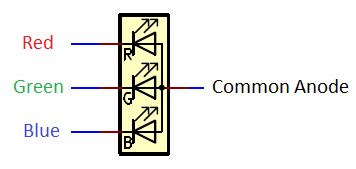
If you are using Common Cathode then you need to use three forward bias Resistors and only one forward bias Resistor for Common Anode. Positive supply Voltage will drive each LED in Common Cathode (Cathode Must be biased with GND) and Ground supply will drive each LED in Common Anode (Anode Must be biased with 3.3V).
To make Red, Green and Blue Light blink separately connect RGBs CC pin to GND of Arduino board and connect R,G,B pins to Arduino Digital pins 11, 12 and 13 through 220Ω Resistor in each terminals, that’s it wiring done. Now Upload the following code to make it blink.
RGB LED Blink Arduino Code
/* RGB LED Blink Code from theorycircuit.com */
const int redPin = 11;    // Define pin for red color
const int greenPin = 12;  // Define pin for green color
const int bluePin = 13;   // Define pin for blue color
const int blinkDuration = 1000; // Blink duration in milliseconds

void setup() {
  pinMode(redPin, OUTPUT);    // Set red pin as an output
  pinMode(greenPin, OUTPUT);  // Set green pin as an output
  pinMode(bluePin, OUTPUT);   // Set blue pin as an output
}

void loop() {
  // Blink red LED
  digitalWrite(redPin, HIGH);   // Turn on red LED
  delay(blinkDuration);         // Wait for blink duration
  digitalWrite(redPin, LOW);    // Turn off red LED
  delay(blinkDuration);         // Wait for blink duration

  // Blink green LED
  digitalWrite(greenPin, HIGH);   // Turn on green LED
  delay(blinkDuration);           // Wait for blink duration
  digitalWrite(greenPin, LOW);    // Turn off green LED
  delay(blinkDuration);           // Wait for blink duration

  // Blink blue LED
  digitalWrite(bluePin, HIGH);    // Turn on blue LED
  delay(blinkDuration);           // Wait for blink duration
  digitalWrite(bluePin, LOW);     // Turn off blue LED
  delay(blinkDuration);           // Wait for blink duration
}
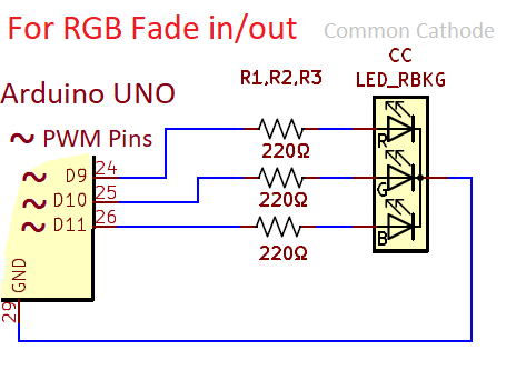
RGB LED Fade in Fade out with Arduino
To make Fade effect in LED color, we need PWM pins of Arduino, so we have to reconnect all three color pins to the PWM pins available in the Arduino UNO board. Here we have used Digital pins 9, 10 and 11.
RGB LED Fade Arduino Code
/* RGB LED Fade in Fade out Code from theorycircuit.com */
const int redPin = 9;    // Define pin for red color
const int greenPin = 10;  // Define pin for green color
const int bluePin = 11;   // Define pin for blue color
int brightness = 0;       // Initialize brightness variable

void setup() {
  pinMode(redPin, OUTPUT);    // Set red pin as an output
  pinMode(greenPin, OUTPUT);  // Set green pin as an output
  pinMode(bluePin, OUTPUT);   // Set blue pin as an output
}

void loop() {
  // Fade in red
  for (brightness = 0; brightness < 255; brightness++) {
    analogWrite(redPin, brightness);   // Set red brightness
    delay(10);  // Wait for 10 milliseconds
  }

  // Fade out red
  for (brightness = 255; brightness >= 0; brightness--) {
    analogWrite(redPin, brightness);   // Set red brightness
    delay(10);  // Wait for 10 milliseconds
  }

  // Fade in green
  for (brightness = 0; brightness < 255; brightness++) {
    analogWrite(greenPin, brightness);   // Set green brightness
    delay(10);  // Wait for 10 milliseconds
  }

  // Fade out green
  for (brightness = 255; brightness >= 0; brightness--) {
    analogWrite(greenPin, brightness);   // Set green brightness
    delay(10);  // Wait for 10 milliseconds
  }

  // Fade in blue
  for (brightness = 0; brightness < 255; brightness++) {
    analogWrite(bluePin, brightness);   // Set blue brightness
    delay(10);  // Wait for 10 milliseconds
  }

  // Fade out blue
  for (brightness = 255; brightness >= 0; brightness--) {
    analogWrite(bluePin, brightness);   // Set blue brightness
    delay(10);  // Wait for 10 milliseconds
  }
}
Image