Last Updated on March 16, 2024
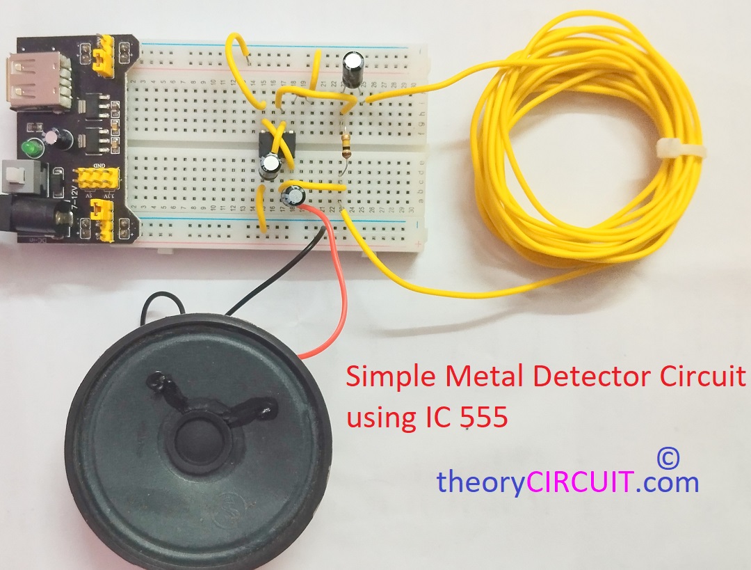
You may aware that metal detectors are used in Security screening, Archaeology, Mining, Treasure Hunting and underwater exploration etc., depends on the applications metal detectors are made with different methods to identify the metals. Sensitivity of detector device is depends on the sensing area and complexity. Here is the easy to construct Simple Metal Detector Circuit using IC 555. In the following circuit we are going to use Inductive method to detect metals by using Parallel R and Series LC tank circuit.
Here the Timer IC 555 Oscillates Square pulse at 50% duty cycle and LC tank circuit uses this pulse as signal source. We know that when ever the electric signal pass through an inductor then it will produce electromagnetic field. This electromagnetic field changes when we bring metal near to the inductor and hence the LC tank circuit reacts to the metal interference, changes in LC tank signal affects trigger input of timer IC and produce difference in the audible sound difference through speaker.
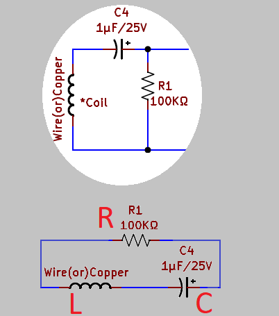
By this method we can identify the metal interference. Use 25V rating 1μF Electrolytic capacitor and Copper or Wire with 25 turns to 100 turns in minimum 6 cm diameter for LC tank circuit.
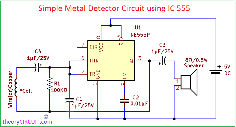
Circuit Diagram
Prototype Video
Components List
- Timer IC NE555P
- Speaker 8Ω/0.5W
- Resistor 100KΩ
- Electrolytic Capacitor 1μF/25V = 3
- Disc Capacitor 0.01μF
- Insulated Copper Coil or Wire (100 Turns with 6 cm diameter)
- Battery
Construction & Working
Make the LC Tank setup as mentioned in the introduction after that configure timer IC 555 as 50% Duty Cycle Astable Oscillator, Here Discharge pin (7) of timer IC is kept open and C1 timing Capacitor is connected to the output through R1 Resistor C1 is now charging and discharging through the same resistor R1 in across with LC tank circuit, discharging and charging time will differ based on the tank circuit signal.
Initially half the level of VCC is flows through tank circuit and triggers timer IC 555 to oscillate square pulse at 50% duty cycle and speaker will starts to give beep sound, whenever a metal piece interference then coil (L), that will change the inductance and makes the time difference in charging and discharging of C1 capacitor, this changes reflects in the sound produced by loud speaker at the output.
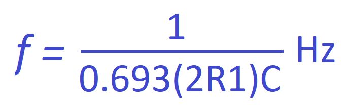
Output frequency of oscillations for the 50% Astable 555 Oscillator can be calculated as,
Notes:
- Sensitivity of this circuit is depends on the L (Coil), use insulated copper coil for better sensitivity.
- Use Electrolytic Capacitor with 25V rating for C1, C3, C4.
- This circuit can be operated with 5V to 6V DC supply. Use Voltage regulator if you are applying above 6V DC supply.
- Use different Value of C1 capacitor from 1μF to 100μF for suitable audio frequency output.
- Diameter and turns in the Coil defines the sensitivity.