Last Updated on November 20, 2024
Most useful Timer IC 555 is widely used as a Astable Multivibrator that generates continuous output pulse without any triggering input. This output Pulse Duration and duty cycle is depends on the Timing Resistors (R1 and R2) that is connected between Discharge pin (7) and bias then Threshold Pin (6), Trigger pin (2) . Then Timing Capacitor (C) that is connected between Threshold pin (6) – Shorted Trigger pin (2) and to Gnd supply. By varying this element value we can change the output pulse duration and duty cycle. Here is the Simple IC 555 timer Astable Multivibrator Circuit Calculator to calculate either R, C or Pulse Duration period.
555 Timer Astable Multivibrator Calculator
IC 555 timer Astable Multivibrator Circuit
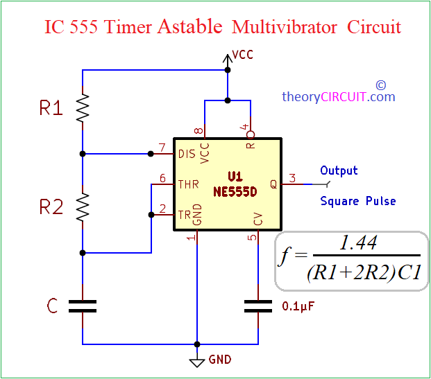
This Astable Multivibrator circuit constructed by using Timer IC 555, It can be called as free running multivibrator, Here the timing components (Resistors) R1, R2 and (Capacitor) C1, gets charging and discharging continuously and creates continuous cycle of oscillation. Here VCC pin and Reset pin connected with positive supply, R1 resistor is connect between Discharge pin and positive supply, R2 resistor is connected between discharge pin and Shorted Threshold, Trigger pin. C Capacitor is connected between (THR, TR) pin and GND.
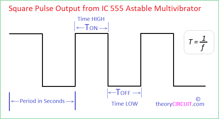
The capacitor C begins to charge through Resistor R1 then Discharge pin 7 and R2, as the voltage across the capacitor reaches 2/3 of the Power supply (VCC) then the internal flip flop of the 555 timer changes its state, this causes the discharge pin 7 to go LOW and then the Capacitor C starts to discharge through Resistor R2 and the discharge pin 7. When the voltage across the capacitor decreases to 1/3 of power supply (VCC) then the internal flip flop changes its state again and the Discharge pin 7 goes HIGH, this cycle of charging and discharging repeats and generates Continuous Square pulse at output pin.
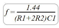
The Formula used by this calculator to calculate Output Pulse Frequency and Time period is, f=1/T.
For TON and TOFF Calculation.
TON = 0.693*(R1+R2)*C
TOFF = 0.693*R2*C
T = TON + TOFF = 0.693(R1+(2*R2))C
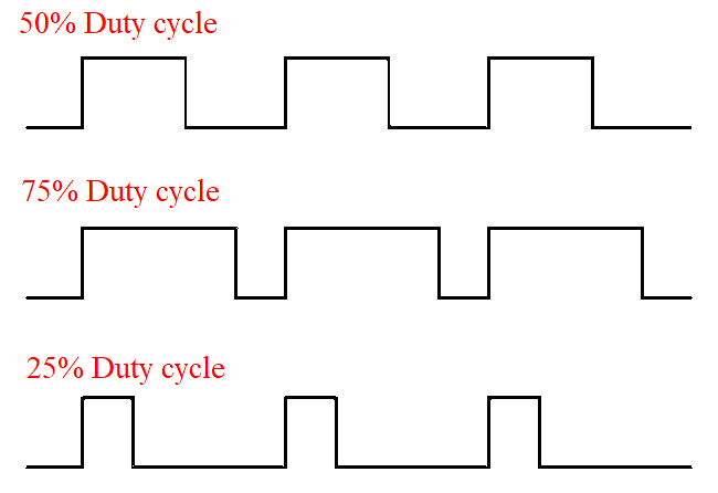
For Duty Cycle Calculation.
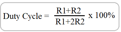
Another Way to calculate Duty Cycle from Time is., Duty Cycle = (TON / T) * 100.
In a Square wave Duty cycle is the ratio of TON compared to the TOFF and denoted in Percentage (%), if Duty cycle is 50% means there 50% TON and 50% TOFF. If Duty cycle is 25% means there is 25% ON time (TON) and 75% OFF time (TOFF).
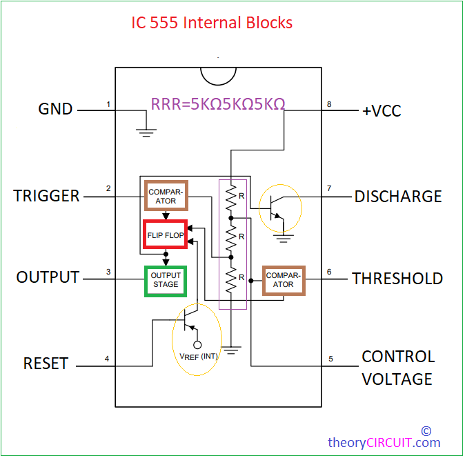
IC 555 Pinout