Last Updated on March 16, 2024
Colorful EL Wires are attractive and Eye Catching Gadget but this wire requires high Frequency AC Supply to operate and produce high intensity luminance. So we always need bulky adapter, for an small size applications or handheld applications like toys, clothing or back bags we need small size and compact Inverter device. Here this Article helps you to build simple DIY EL Wire Inverter circuit by using IC 555 timer.
What is EL Wire?
If you are not aware about EL wire you may ask, What is EL Wire?
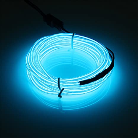
Electroluminescent wire often abbreviated as EL wire is a thin copper wire coated in a phosphor that produces light through electroluminescence when an alternating current with high frequency is applied to it.
Electroluminescent wire (EL Wire) Structure
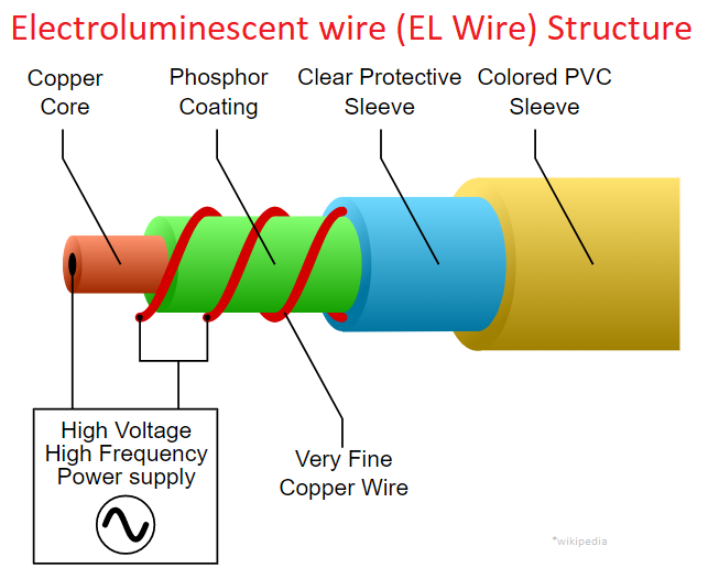
This EL wire Contains Five layers starting with copper core then phosphor coating then very thin Copper wire, in these two conductive Copper wire we apply High Voltage, High frequency power supply, due to it phosphor starts to illuminate. Clear protective sleeve and Colored PVC sleeve covers copper wires and gives Colored illuminance.
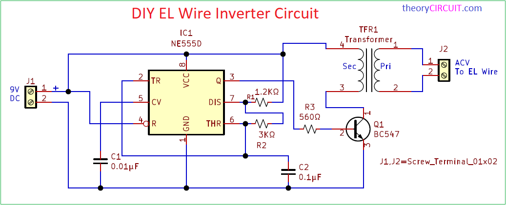
Circuit Diagram
Components Required (BOM)
| 1 | C1 | 0.01µF | C_Disc_D3.0mm_W1.6mm_P2.50mm | 1 | ||
| 2 | C2 | 0.1µF | C_Disc_D3.0mm_W1.6mm_P2.50mm | 1 | ||
| 3 | R1 | 1.2KΩ | R_Axial_DIN0204_L3.6mm_D1.6mm_P7.62mm_Horizontal | 1 | ||
| 4 | R2 | 3KΩ | R_Axial_DIN0204_L3.6mm_D1.6mm_P7.62mm_Horizontal | 1 | ||
| 5 | R3 | 560Ω | R_Axial_DIN0204_L3.6mm_D1.6mm_P7.62mm_Horizontal | 1 | ||
| 6 | IC1 | NE555D | DIP-8_W7.62mm | 1 | ||
| 7 | Q1 | BC547 | TO-92_Inline | 1 | ||
| 8 | TFR1 | Transformer | 1300 : 8 Ohm Audio Transformer EE14 Transformer Audio POS Transformer | 1 | ||
| 9 | J1 | Screw_Terminal_01x02 | TerminalBlock_Altech_AK300-2_P5.00mm | 1 | ||
| 10 | J2 | Screw_Terminal_01x02 | TerminalBlock_Altech_AK300-2_P5.00mm | 1 |
Construction & Working
Here Inverter Circuit Formed by using Timer IC 555 and Audio Transformer Specified as (1300 : 8 Ohm Audio Transformer EE14 Transformer Audio POS Transformer). IC 555 Configured as Astable Multivibrator and it will produce 2KHz Frequency of Oscillation. This output Pulse connected with Audio Transformer through Switching Transistor BC547 at the Secondary winding (8 ohms side). At the Primary side of Audio Transformer we can obtain AC voltage with 2KHz Frequency. (Check All the output Voltage and frequency during Prototype). In this Astable Multivibrator Circuit R1, R2 and C2 acts as a timing Elements and these components decides the output frequency of IC 555. This Circuit works with 9V battery as a power source.
Printed Circuit Board
DIY EL Wire Inverter Circuit PCB Gerber Files.

Interactive Board Viewer

