Last Updated on March 16, 2024
Soldering is an art in Electronics, when we solder components in PCB or dot board it produces smoke and fumes which is toxic and dangerous to human health to avoid this situation here is the circuit given with easily available components, hence you can do it yourself.
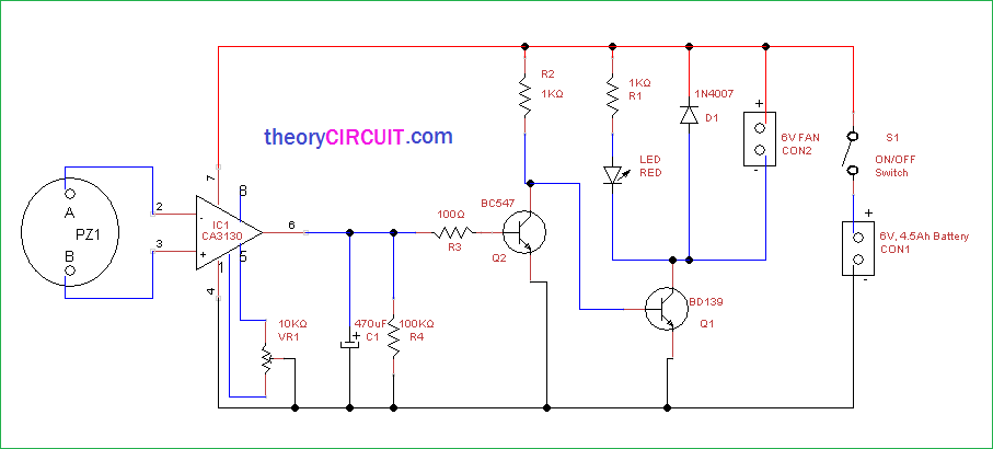
Circuit Diagram
Construction & Working
In this circuit 6V DC fan working as smoke and fumes exhaust device and this fan runs only when we solder components, here the 6V 4.5 Ah rechargeable battery is used to provide bias. If you have workbench then you can use DC power source, The piezo element is placed to produce electrical difference due to heat from soldering iron (Make a heatsink on piezo element).
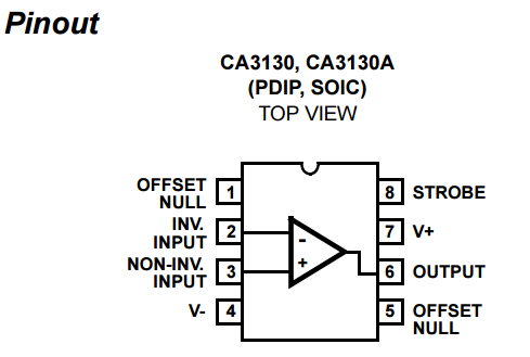
The piezo element connected in inverting and non-inverting terminals of BiMOS Operational Amplifier CA3130, the variable resistor VR1 used to vary the offset, the output from operational amplifier connected to the transistor Q2 BC547 and directed to BD139 bi-junction transistor and then output indicator LED and 6V fan connected in the collector terminal of BD139 followed through +Vcc.