
Last Updated on March 16, 2024
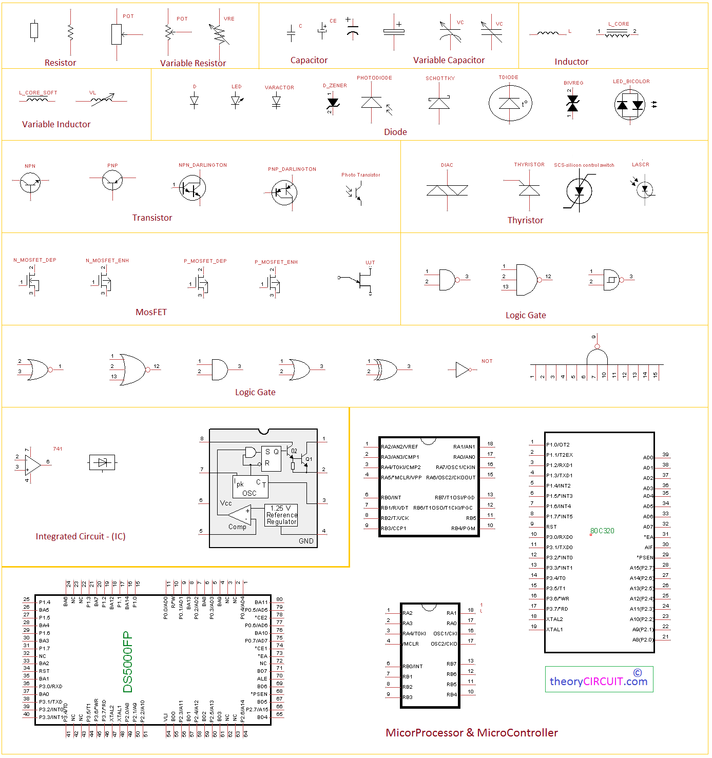
The Symbols are very important to represent Electronic components in a circuit diagram, without electronic symbol the design of circuit and schematics are very difficult and also knowing the components is very must to read the circuit diagram representation.
Symbols
Even More…
The electronic Components have terminals and each will have its own name and polarities. The Basic is Passive and Active components, R C L (Resistor, Capacitor, Inductor) are passive and Most of the Semiconductors are Active components.
Resistor
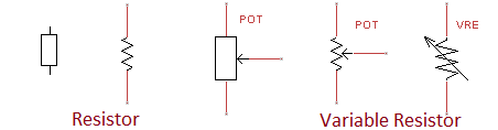
Resistor component gives resistance that is barrier to the current flow in a circuit. There are two different symbols are widely used in schematics that is Zigzag format (US style) and Rectangle shape, this will have two pins and three pins if variable resistor. Unit of resistor is Ohm Ω.
Capacitor
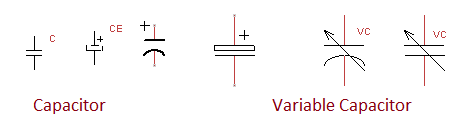
The capacitor reacts as static energy storage some times, Non-polarized (two parallel line) capacitor have two equal plate separated by insulator and Polarized (one straight and one curved line) capacitor have positive and negative pins.
Inductor
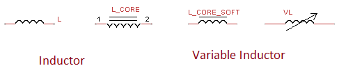
The Inductor reacts as magnetic storage element, it is represented as loopy coils, or curved bumps. This element don’t have polarities.
Diode
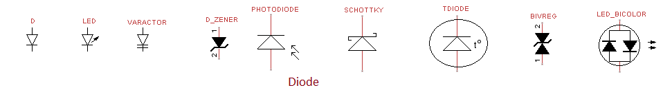
The Active devices are starts from diode, symbol represented with Triangle Arrow pressed up against a line. The diode have polarities called Anode(triangle pin) and Cathode(straight line) hence it should be identified for employment.
Transistor
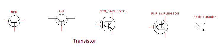
This components transfers resistance between two circuits (…hmm from theory) based on the layers it is called as NPN or PNP and also it is named as BJT (Bi Junction Transistor).
Thyristor
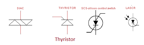
Thyristors are active device having more than two junction in layer structure and used in high voltage and high power applications.
MosFET
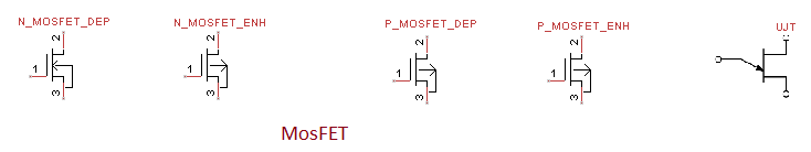
Metal oxide semiconductor field effect transistor is the expansion of MosFET, these are reacts as voltage control device having three terminals. Based on the diffusion it is classified as Depletion and Enhancement and depends on the channel it is classified as N and P channel MosFET.
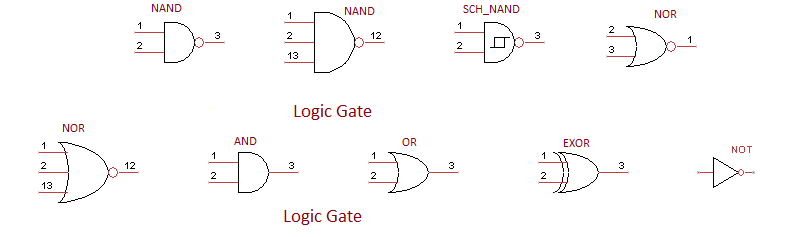
Logic Gates are comes in a Integrated Circuit (IC) format for an example IC7400 (four nand gates), The Logic operations are AND, OR, NOT, EXOR, NAND, NOR having unique symbols. Based on the requirements we can choose two, three are more input output pin logic gates.
Integrated Circuit
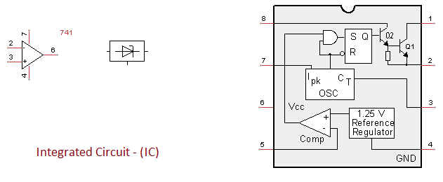
The Integrated Circuits (IC) are represented in many ways but mostly with big arrow for operational amplifier or square box with pin functions. (more…)
Switches
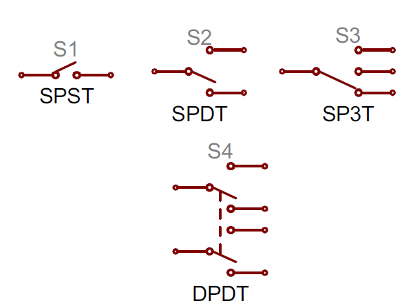
Switches makes circuit connected or disconnected (ON or OFF), depends on the number of poles and throws it is classified. Other than this push button and toggle switches are also available in circuit diagram.
Power Supply
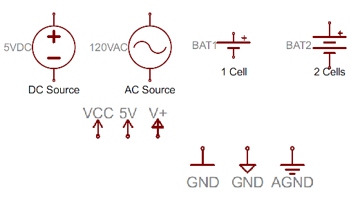
These are represents Power supply and bias details in circuit diagram. Symbol with + and – indicates DC (direct current) source and symbol with sin wave indicates AC (alternating current) source.
Crystal and Resonators
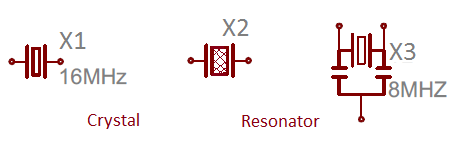
Crystal and Resonators are important to produce clock pulse for microcontrollers and other circuit. Different range of crystal available and the range is represented in circuit it self. The crystal will have two terminals when we connect two capacitors and make three terminals then it becomes resonator.
Connectors
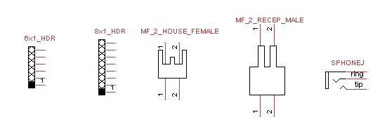
Connectors, Headers and Jack are connects two different device and helps to transfer information or supply or signals. Some connectors are termed as Male and Female connectors.
Fuse
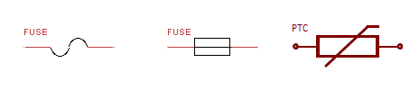
The Fuse reacts as safety element to protect circuit against large current and sudden urges of current. The fuse are comes in different structure and different materials the basic symbol given here, PTC represents positive temperature coefficient (temperature dependent resistor) and it is also reacts as fuse.
Transformer
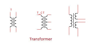
The Transformer is step down or step up the voltage and current, for electronic circuits we use Step down and isolation transformers mostly in some other case like inverter we use step up transformer. Transformer with two terminal secondary and three terminal (center tapped) secondary are illustrated.
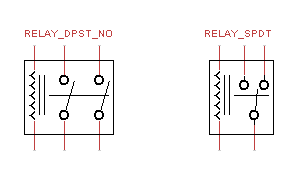
The Relay are Electro magnetic Switches and makes or disconnects circuits when the relay coil gets energy. Depends on the pole and contact relays are classified. Relay Switch gives N/O (normally open) and N/C (normally close) terminals when the relay coil gets energy N/O becomes closed and N/C becomes opened terminals.
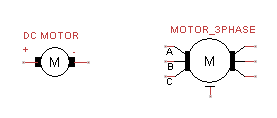 The Circle with letter M represents the Motor, Some times servo motor and stepper motor represented with the names.
Junctions, Jumber and Nodes
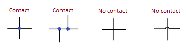
When two wire cross each other in a circuit with out connection it is represented with no dot point (No contact) or with bend in one wire. The wire joint represented with Dot point (Contact).
No devicеs demanded!
Welcome!
you guys are doing great. your write ups have helped me very much in understanding integrated circuits.
keep it up.
Your switch symbols (especially relays) require triangular contacts for spring return contacts!