
Last Updated on March 17, 2024
Simple Current Control Circuit for LED using MAX16832C is designed by using SMD Components, As we know LED (Light Emitting Diode) is a Current driven device. Which glows in Forward bias and blocks reverse bias supply and the color of light emitted by an LED is determined by the energy band gap of the semiconductor material used in the LED. Different semiconductor materials produce different colors of light when they are biased by an forward electric current.
Why we Need Current Control Circuit for LED?
LEDs are semiconductor device with a nonlinear Voltage and Current relationship, a small change in current leads to inconsistent brightness and luminance variation, even slightly higher current than specification of LED can damage the LED device. So that it is very important to have a current control circuit to drive a LED or array of LEDs.
For Constant Current output and also Brightness control, IC MAX16832C from Maxim Integrated company used in the following schematic.
IC MAX16832
The MAX16832A/MAX16832C are 2MHz, High-Brightness LED Drivers with Integrated MOSFET and High-Side Current Sense step-down constant-current high-brightness LED (termed as HB LED) drivers. These ICs suits for automotive interior/exterior lighting, architectural lighting and ambient lighting, LED bulbs, and other LED illumination applications, it can be a cost effectice solution. These ICs can operate with +6.5V to +65V DC input and can provide output current upto 1 Amps. A high-side current-sense resistor adjusts the output current, and a dedicated pulse-width modulation (PWM) input enables pulsed LED dimming over a wide range of brightness levels. If you are not using PWM signal for brightness control then you can apply above 2.8V to turn the LED current ON below this voltage level will turn OFF the LED current. Refer Datasheet for more Information.
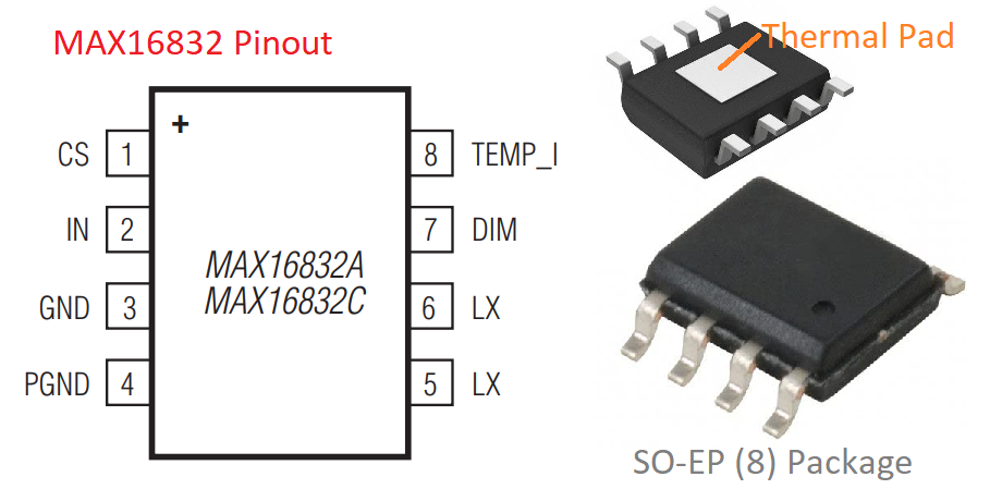
| Pin Number | Pin Name | Description |
| 1 | CS | Current Sense Input pin. |
| 2 | IN | Positive supply voltage input pin. |
| 3 | GND | Ground supply. |
| 4 | PGND | Power Ground. |
| 5 | LX | Switching Node Pin. |
| 6 | LX | Switching Node Pin. |
| 7 | DIM | Logic Level Dimming Input Pin. |
| 8 Thermal pad | TEMP_I Exposed Pad | Thermal Foldback Control and Linear Dimming Input pin. Ground plane for effective power dissipation. |
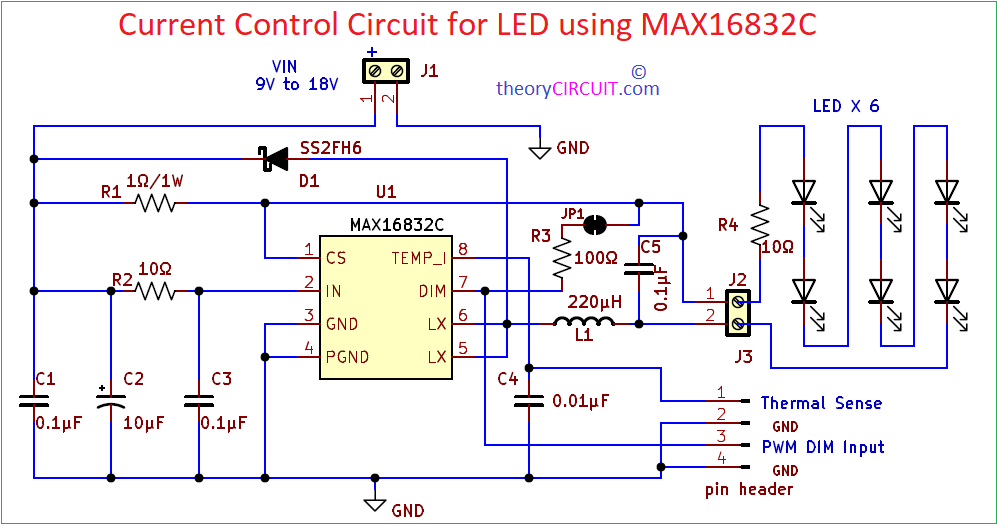
Circuit Diagram
Components Required (BOM) PCB
| 1 | C1, C3, C5 | 0.1μF | C_1206_3216Metric | 3 | ||
| 2 | C2 | 10μF | CP_Elec_4x3 | 1 | ||
| 3 | C4 | 0.01μF | C_1206_3216Metric | 1 | ||
| 4 | R1 | 1Ω/1W | R_2512_6332Metric | 1 | ||
| 5 | R2 | 10Ω | R_1206_3216Metric | 1 | ||
| 6 | R3 | 100Ω | R_1206_3216Metric | 1 | ||
| 7 | L1 | 220μH | L_12x12mm_H8mm | 1 | ||
| 8 | D1 | SS2FH6 | D_SMF | 1 | ||
| 9 | U1 | MAX16832C | Diodes_SO-8EP | 1 | ||
| 10 | JP1 | SolderJumper Bridged | SolderJumper-2_P1.3mm_Bridged_Pad1.0x1.5mm | 1 | ||
| 11 | J1, J2 | Screw_Terminal_01x02 | TerminalBlock_Altech_AK300-2_P5.00mm | 2 | ||
| 12 | J3 | pin header | PinHeader_1x04_P2.00mm_Vertical | 1 |
Construction & Working
This circuit designed to make PCB prototype and all the components used in this circuit are SMD (Surface Mount Devices) components. LEDs are not include in the PCB you have to connect LED array in J2 Screw terminal block. There is Solder Jumper JP1, Which connects 100Ω Resistor with DIM to provide Logic HIGH input (above 2.8V) to turn ON LED current and the Brightness of the LEDs will not change. If you want to Control the brightness level then break this Solder Jumper JP1 and apply PWM Signal to PWM DIM Input pin at J3 Pin header. Use external PWM Oscillator with variable Duty cycle control for brightness adjust.
The MAX16832C supports various dimming method as previously said, including analog dimming and PWM (Pulse Width Modulation) dimming. Analog dimming involves applying a voltage signal to the DIM pin above 2.8V DC for continuous adjustment of LED brightness. PWM dimming to control the average current flowing through the LEDs, PWM Signal enables precise and rapid brightness adjustments.
The primary function of MAX16832C is to regulate the current flowing through the connected LEDs. The IC utilizes an external sense resistor called RSENSE (here we have used 1Ω/1W) through which the LED current flows. By monitoring the voltage drop across this resistor, the IC regulates the current to a constant value, ensuring a consistent brightness level for the LEDs.
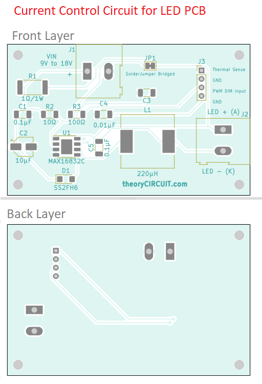
Printed Circuit Board
Current Control Circuit for LED using MAX16832C PCB Gerber files.
Interactive Board Viewer

