Last Updated on March 16, 2024
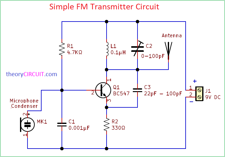
Simple Voice FM Transmitter Circuit designed by using single NPN BC547 Transistor. This mini FM transmitter circuit will broadcast FM signal to considerably long distance. This FM Transmitter circuit designed for Voice input through Condenser Microphone, If you want to transmit direct Audio Signal then remove condenser mic and apply Audio signal to the base terminal R1 Junction.
By using long wire or Aerial antenna we can increase the distance of FM Transmission. Trim Capacitor C2 and L1 decides the Carrier Frequency of FM signal and always choose free to use non commercial FM bands.
Circuit Diagram
Components Required
- Condenser Mic
- Transistor BC547 npn
- Trim Capacitor 100pF
- Capacitor 0.001µF, 22pF each one
- Aerial antenna or single stranded wire
- Inductor 0.1µH
- Resistor 4.7KΩ, 330Ω each one
Construction & Working
This Single Transistor Voice FM Transmitter circuit can produce FM Carrier signal from 50MHz to 160MHz by using the C1 and C2 tank circuit. Here Transistor BC547 configured in common emitter and input signal is taken from condenser mic. If you want fixed transmission carrier then calculate FM tank oscillation (L1, C2) and choose the elements according to your need.
This circuit operates with 9V DC supply and well designed to work with 9V battery power supply also, due to single transistor and all passive external components this FM transmitter circuit will consume very low power.
Note: Choose Free to use and open to public FM carrier range do not tune this circuit to the commercial FM band according to your country.
