Last Updated on March 16, 2024
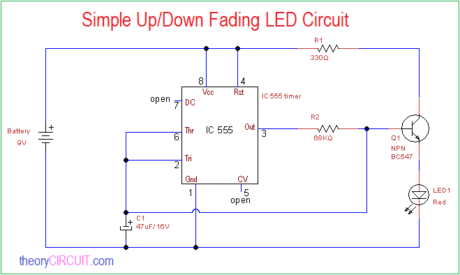
Lot of colorful projects rises when LED and timer IC meets, Here the Simple Up/Down Fading LED Circuit is designed with timer IC 555 to produce breathing light effect through LED. We don’t need costlier PWM circuit or driver IC to produce fading light, the following simple circuit is enough to give fading LED effect.
This circuit is constructed by using timer IC and few easily available components. In this prototype we tested single Red LED, you can connect up to three LEDs in this circuit, make sure to apply proper bias to this circuit.
Circuit Diagram
Components Required
- IC 555
- Transistor BC547
- Resistor 330Ω, 68KΩ each 1
- Capacitor 47μF / 16V
- LED
- 9V Battery
Construction & Working
This simple Up/Down Fading LED Circuit employs IC 555 as a Astable multivibrator hence it produce continuous timing pulse, output pulse is connected to the timing capacitor C1 through R2 Resistor. Threshold and trigger pins are also connected with timing capacitor C1.
Target LED is connected to the Q1 transistor emitter and this transistor collector terminal is connected with battery through R1 Resistor. Output from timer IC is applied to the Q1 base through R2 Resistor.
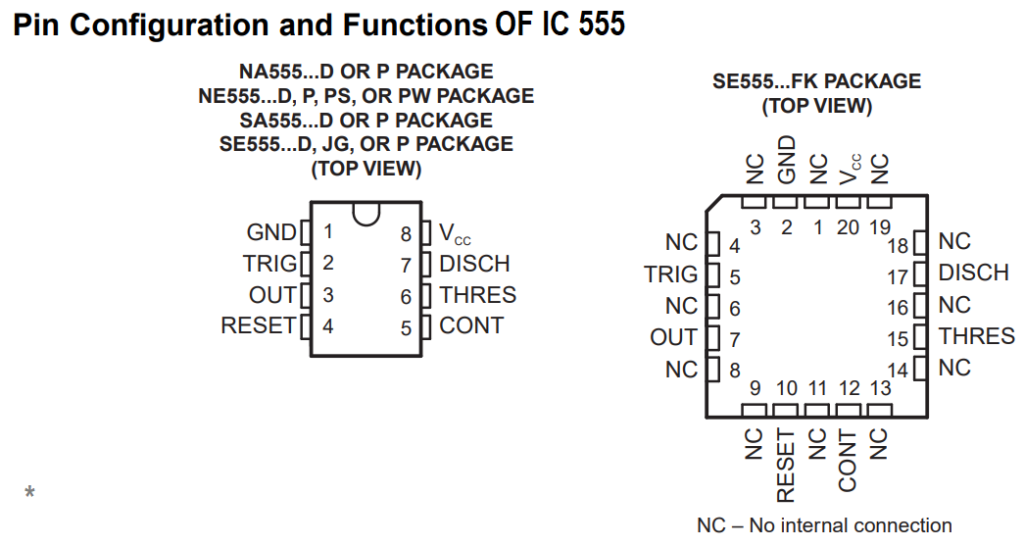
IC 555 timer pin details
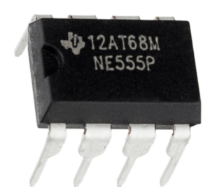
Physical structure of IC 555
When we apply power supply to this circuit through 9V battery, the IC 555 starts to oscillate the square pulse depends on the timing Resistor and Capacitor, but here we provide only capacitor C1 to the timer IC and also it can be charged through only output signal. Initially output of timer is high so the transistor turn ON and makes LED glow, during that time slowly C1 capacitor gets charge and makes the timer output low and Q1 transistor becomes saturation but the capacitor charge slowly gets discharge through transistor Q1 to LED so the LED glows bright to dimmer level, these process occurs continuously up to the presence of power supply to this circuit.


i could not get this circuit to fade up / down
My first circuit was worked but second and third wasn’t. Because first 555 IC different the others. HA17555 IC code is not worked. Please try change the IC.As a result the circuit is good working.
Something’s not right with your circuit, it fades on then stays on, does not fade off again