
Last Updated on April 2, 2024
Timer IC 555 can be a toy for learners, tool for professionals and can be a usefull device for electronic applications. In this article we are going to experiment Simple Traffic Light Circuit using IC 555 and three color LEDs (Red, Yellow, Green), As we know Traffic light signs are very important for road safety.. It is going to be a model and experimental traffic sign project, which is very interesting and a easy project to make.
This circuit starts with Green signal light and keep it ON for some time duration and then turns ON Yellow color LED for short duration and the Turns ON Red LED and keep it ON for some time duration and this cycle continuously runs. You can interchange Red, and Green LEDs for to start with Stop Signal that is Red color light.
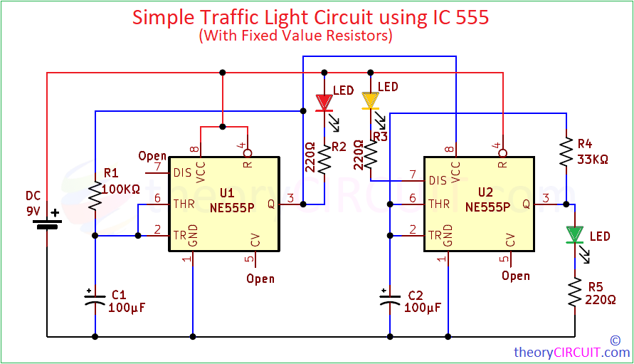
Circuit Diagram
Components Required
- Timer IC 555 = 2 (should be same type)
- LED Red, Yellow, Green each one
- Resistor 220Ω = 3
- Resistor 100KΩ, 33KΩ each one
- Electrolytic Capacitor 100μ = 2
- Connecting wires
- Breadboard
- DC Power supply 9V
Working Video
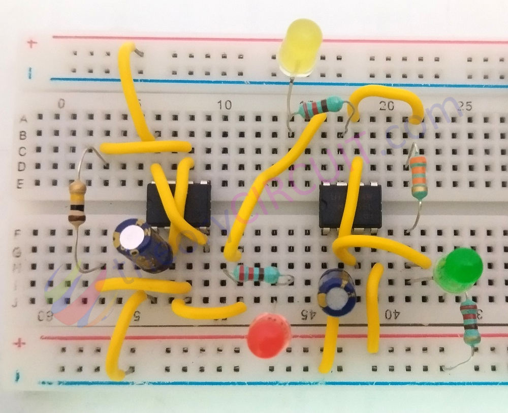
Construction & Working
In previous Traffic Light Circuit We used Variable Resistor to control ON time of each LED in traffic signal. But it requires proper biasing and tuning in Variable Resistor to get desired output. So here is the simple and fixed value Resistor based Traffic signal circuit. For to make time difference you need to calculate and choose R1 and R4 Resistor. Here we picked 100KΩ (R1) and 33KΩ for (R4) to give approximately ten seconds time for Green and Red LEDs. Here Second stage timer IC gets bias through First stage output, so that you can change the whole timing (Red & Green only) by changing R1 Resistor. For accurate 555 timer calculation use this Calculator.
This traffic light circuit having two stage timer IC 555 is configured as dual Astable multivibrator and the second stage IC (having Green LED at output) gets positive supply through output pulse of first stage (having Red LED at output). Both stage output pins are connected as feedback to the Threshold and Trigger input.
During the initial time, when we power (9V to 12V / 500 mA) ON, Timer IC U1 gives High Output because the trigger pin voltage is less the one third of VCC (1/3). Meanwhile C1 takes time to get charge through R1 Resistor. Here Red LED stay in OFF because of its connected polarity and Stage two Timer U2 IC 555 gets bias nearly 4.5V to 5V and This timer also having 1/3 of supply in trigger pin and so internal flip-flop in set condition and gives high output, so the Green LED glowing. This is up to Capacitor C2 gets charge to 2/3 of supply voltage after reaching that threshold limit internal flip-flop goes to reset then output goes to 0 (Low) and Green LED turns OFF. Now the Charge in the Capacitor C2 gets discharge through internal transistor, here in pin 7 (Discharge pin) we have already connected a Yellow color LED, so that this LED glows for short duration (up to full discharging of C2).
For stage one U1, the Capacitor C1 gets charge slowly through R1 (because it is connecte to output pin), when it reaches 2/3 of VCC to U1, then Threshold pin detects by using internal comparator and makes internal Flip-flop to Reset and gives Low (0) at output. Now the Red led gets turn ON and it last for up to C1 gets discharge through internal transistor. The above operation continuously happens and gives timed traffic signal through LEDs. (Red for STOP, Yellow for READY, and Green for GO!).
Hello mate , i tried copying the 555 timer circuit into circuit wizard. i double checked it over and ver again , but it simulates weird. it goes to green then yellow , green and then red and then green. let me know what i can do please.
Hello Emanuel Stanciu,
Which usually points to a wiring or component issue. Double-check all connections, especially VCC (pin 8) and GND (pin 1), and ensure pins 2 and 6 are connected for Astable mode. Also, make sure the reset pin (pin 4) is tied to VCC, and check your resistor and capacitor values. Sometimes a small error or a floating pin can cause unstable simulation.