
Last Updated on March 16, 2024
This Circuit helps you to find Open Earth, Phase or Neutral reverse in the Power source. By using simple components like Resistors and LEDs, we can create this circuit.
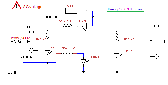
Circuit Diagram
Construction and Working
Four Red color LEDs are used here, and Resistors are 56KΩ / 1W. LED1 is connected between Phase and Earth through Resistor.( Here you can connect LED in any Polarity).
LED2 is connected between phase and Neutral. LED3 is connected between Earth and Neutral.
These three LEDs will show the condition of AC power supply.
LED Indication
| LED1 | LED2 | LED3 | LED4 | Status |
| ON | ON | OFF | – | Phase Neutral Earth Wired Correctly |
| OFF | ON | ON | – | Wrong Polarity of Phase/Neutral |
| ON | ON | ON | – | Open Earth or Neutral |
| – | – | – | ON | Blown fuse |
LED 4 connected parallel to the fuse and it glows when fuse blown and appliance being connected the power source.
Some spike and surge protector use MOV (Metal Oxide Varistor) along with this kind of circuit to protect appliance from high voltage and surge current.
How fuse blow LED will glow if fuse blow circuit is floating not complete
It sane in anchor spike guard extension