
Last Updated on March 16, 2024
Every circuit needs perfect bias supply to perform well and some times Integrated circuits or special components or output actuators need negative voltage. After rectification and regulation of main DC supply we cannot produce immediate negative supply. In this prototype article negative voltage generator circuit given with simplified bill of material and it can be easily employed in any circuit schematics.
Before jump into negative voltage generator circuit, first we should know about the negative voltage and separation of negative voltage cycle from a sine wave. When function of sine moves respect to time then it will have both positive and negative cycles. When we use diode clippers we can get negative cycles only or positive cycles only. Here the diode circuit example given for negative cycle output.
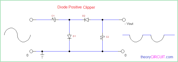
Diode Clipper Theory
In this circuit diode D1 conducts (after 0.7V) during the positive cycle and brings signal to Ground, D2 in off condition. During the negative cycle D2 diode conducts signal and brings to output, but D1 turns to off condition, by the way every positive cycle grounded and only negative cycle comes to output.
Negative Voltage Generator circuit Using IC 555
An astable multivibrator oscillator circuit implemented by using timer IC 555 and then output square pulses are separated as negative output by using diode clipper.
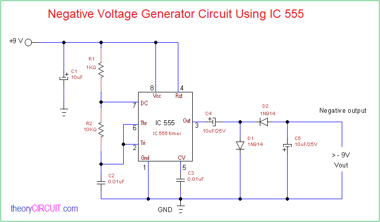
Construction & Working
In this circuit signal oscillator is Astable multivibrator and then voltage converter is diode clipper. When we apply bias to this circuit IC 555 gives square wave output with positive and negative levels through pin3, when square pulse reach diode clipper, positive pulse grounded and negative pulse only conducted to output as mentioned in diode clipper theory.
Negative voltage Converters
Here some negative voltage converter ICs are listed, by using these IC we can reduce the bill of material cost and these ICs are comes in different package styles.
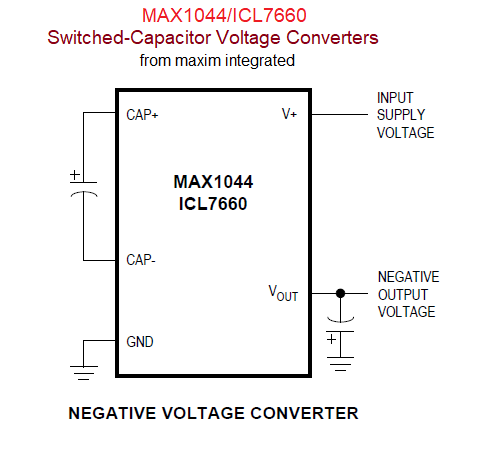
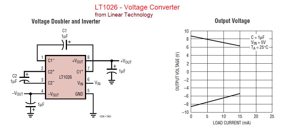
these DC-DC voltage converters don’t need separate oscillators and requires only few external capacitors, refer datasheets for more information.
I would like to find out that why do we need the NEGATIVE voltage in electronic circuits
Tanks in advance.
Op amp power supply if you want a oscillation
Usually with sensors we sometimes use -10V to +10V. Imagine an analog joystick making a radio control car moving forward and backward, this analog joystick can use the 0V to 10V for moving forward and 0 to -10V for reverse.
Hope this helps