
Last Updated on March 16, 2024
In today’s fast pace digital age, the demand for efficient and reliable wireless solutions has increased to the sky high. Now imagine controlling your home appliances or any industrial equipment with just a simple click, without the hassle of physical wires. Wireless Switch using RF ASK Module can achieve this in reality. Yes 433MHz RF ASK modules are most underated wireless transmitter and receiver device. It can be employed in any circuits that require wireless logic transfer.
Wireless Switch using 433MHz RF ASK Module can be used in multiple ways here we plotted two example circuits that can be easily modified to you application requirements. Lets start with the pinout details of 433MHz Transmitter Receiver RF module.
FS1000A 433mHz Transmitter Receiver Pinout
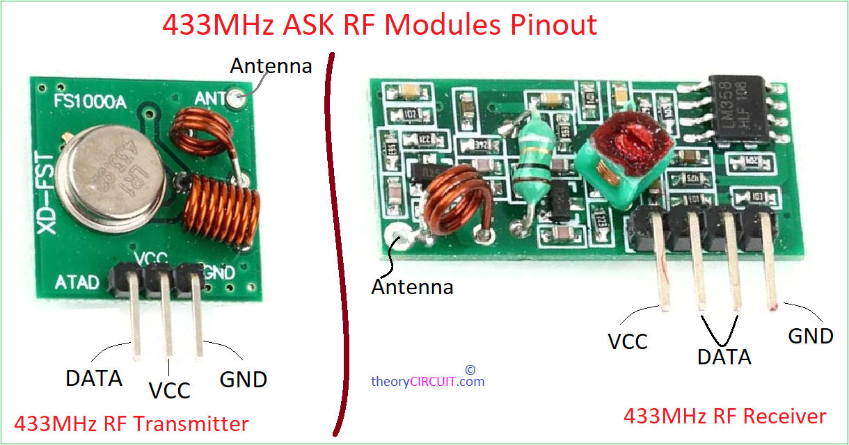
This 433MHz ASK module Produced by various manufacturers. In many ASK Modules this FS1000A is a popular RF Transmitter, Receiver among them. The transmitter/receiver (Tx/Rx) pair operates at a frequency of 433 MHz that is why this is called as 433MHz module. RF transmitter receives serial data in Data pin and transmits it in ASK (Amplitude Shift Keying) RF wave wirelessly through its antenna. Transmission rate of this module lies between 1Kbps to 10Kbps. At the other end Receiver module works in the Same frequency to receive ASK RF Wave through Antenna and decodes into data. Both modules can work with 2.5V to 6V DC and consumes current up to 6mA. Normal wire or copper coil about 2 inch can be used as antenna. This module transmit signal up to 150 meters. By implementing additional RF boost circuits and antenna we can increase the communication distance.
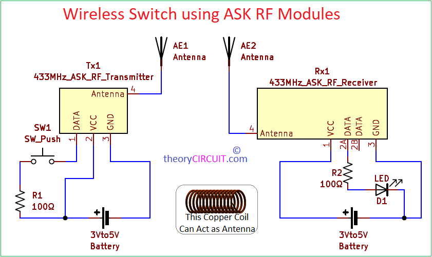
Wireless Switch using 433MHz ASK Modules
Components Required
- 433MHz ASK RF Transmitter Receiver module
- Battery two
- Push button switch
- Resistor 100Ω = 2
- Antenna wire
- LED
Construction & Working
Construction of this circuit is very simple, Connect Push button switch to the data input pin through R1 resistor and connect R1 to the VCC. Connect power supply pin VCC and GND to the power supply source either battery or regulated power supply. When the button pressed it pass VCC as Logic HIGH data to the data pin. RF transmitter circuit modulates that data in Amplitude shift keying and propagates through antenna.
In Receiver Data pin 2A and 2B both are same pins and gives same data. Hence one data pin is connected with LED and bias applied to the VCC and GND pins. You can connect any output device through ttl level shifter setup in data pins. When the antenna receives signal then its decoded by the internal circuits in the Rx module and given through data pins. Output will be same as input logic send through transmitter.