
Last Updated on July 28, 2026
I keep a little tray on my bench with maybe a dozen of these 0.91 inch OLED screens rattling around in it. They cost next to nothing, I paid around few dollars each the last time I ordered a batch and they end up in half the ESP32 stuff I build. A temperature readout, a wifi status line, a boot counter, whatever the project needs display.
The reason I keep buying them comes down to two things. The display stays sharp even in a lit room, and the data side runs on just two wires. When your breadboard already looks like a plate of noodles, two wires matters more than you’d expect.
This post walks through getting one going, start to finish. We’ll sort the wiring, then the library, then a few sketches – plain text first, then some shapes, then a live number you can drop straight into a real project. I’ll also call out the spots that ate my time when I started, so they don’t eat yours.
What is a 128×32 OLED Display?
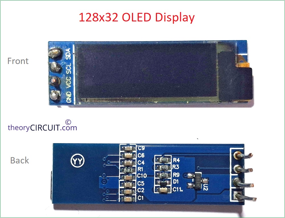
If you are new in tinkering electronics then you may ask What is a 128×32 OLED Display? OLED stands for Organic Light Emitting Diode. Fancy name, simple idea – every pixel makes its own light. There’s no backlight sitting behind it. That’s the whole reason OLED looks so crisp and barely touches your battery.
The “128×32” bit is just the resolution. 128 pixels across, 32 down. That works out to 4096 pixels on a screen that’s roughly 0.91 inch – smaller than your thumbnail.
Running the display here is a chip called the SSD1306. If you’ve ever worked with the bigger 128×64 OLED you may know, it’s the same controller. Only the number of rows changes. It means the code barely changes either.
One thing to know upfront: these are monochrome. Single color. Mine have always been white, but you’ll see blue and yellow ones floating around too. Whatever color your module ships with is what you’re stuck with – there’s no swapping it in software.
Technical Specifications
| Parameter | Value |
|---|---|
| Driver IC | SSD1306 |
| Resolution | 128 × 32 pixels |
| Screen Size | 0.91 inch |
| Interface | I²C (4-pin) |
| Operating Voltage | 3.3 V to 5 V |
| I²C Address | 0x3C (default) |
| Display Color | Monochrome |
See that voltage range? 3.3V to 5V. Worth remembering, because it makes life easy. The ESP32 runs on 3.3V logic, the OLED is perfectly happy at 3.3V, so there’s no level shifter to mess with and no extra parts. Connect and go.
The 4-pin I2C version keeps things simple:
VCC – power, feed it 3.3V
GND – ground
SCL – the I2C clock line
SDA – the I2C data line
Four pins. Two for power, two for data. Can’t really get simpler than that.
Now, some of these modules turn up with 7 pins – that’s the SPI version. Ignore it for today. We’re going with I2C because it’s fewer wires and, honestly, less fuss. Grab the 4-pin module and follow along.
Wiring the OLED to ESP32
The ESP32 has hardware I2C built in on two default pins:
GPIO21 = SDA
GPIO22 = SCL
So the wiring is about as painless as it gets.
Wiring Diagram
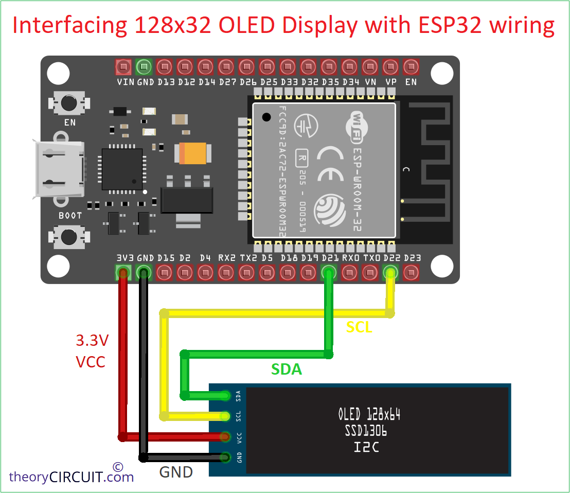
Run VCC to the 3.3V pin, not 5V. Sure, the module can take 5V. But the ESP32 hands you clean 3.3V right there, so why bother with the slightly higher risk? Stick with 3.3V.
Wire up all four. Power on the board. And… nothing on the screen. Because, We haven’t uploaded anything yet. Let’s fix that.
- Step 1: Find the I2C Address
- Step 2: Install the Libraries
- Step 3: Display Your First Text
- Step 4: Display Your Running Text
Step 1: Find the I2C Address
Before we touch any display code, let’s make sure the OLED is even listening. How? A quick I2C scanner sketch.
Most modules sit at address 0x3C. A few use 0x3D instead. This little sketch tells you which one you’ve got, so you’re not guessing.
#include <Wire.h>

void setup() {
  Wire.begin();
  Serial.begin(115200);
  while (!Serial);
  Serial.println("\nI2C Scanner");
}

void loop() {
  byte error, address;
  int nDevices = 0;

  Serial.println("Scanning...");

  for (address = 1; address < 127; address++) {
    Wire.beginTransmission(address);
    error = Wire.endTransmission();

    if (error == 0) {
      Serial.print("I2C device found at address 0x");
      if (address < 16) Serial.print("0");
      Serial.println(address, HEX);
      nDevices++;
    }
  }

  if (nDevices == 0)
    Serial.println("No I2C devices found");
  else
    Serial.println("Done.");

  delay(5000);
}
You may get output in the serial monitor of Arduino IDE like this,
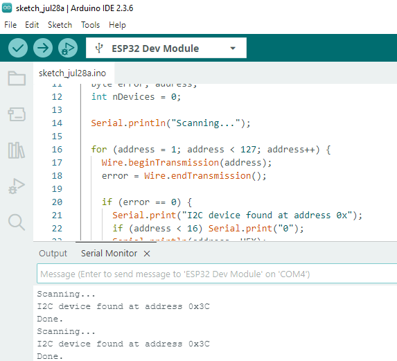
So we confirmed that our display I2C address is 0x3C.
Step 2: Install the Libraries
We need two libraries here for better text shapes and graphics, both from Adafruit:
Adafruit SSD1306 – handles the display controller.
Adafruit GFX – does the drawing: text, lines, circles, all of it.
You may know how to install library, if you can’t remember – Open the Arduino IDE, head to Sketch > Include Library > Manage Libraries, and search “Adafruit SSD1306”. Install it. When it pops up asking about dependencies, hit Install All — that grabs the GFX library too, so you don’t have to hunt it down separately.
Step 3: Display Your First Text
Here’s the classic first sketch. The one detail that actually matters for our display: SCREEN_HEIGHT is 32. That’s the single line you’d change if you were coming from the 128×64 code.
#include <Wire.h>
#include <Adafruit_GFX.h>
#include <Adafruit_SSD1306.h>

#define SCREEN_WIDTH 128
#define SCREEN_HEIGHT 32

#define OLED_RESET -1

Adafruit_SSD1306 display(
SCREEN_WIDTH,
SCREEN_HEIGHT,
&Wire,
OLED_RESET
);

void setup()
{
  Serial.begin(115200);

  if(!display.begin(SSD1306_SWITCHCAPVCC, 0x3C))
  {
    Serial.println("OLED allocation failed");
    while(true);
  }

  display.clearDisplay();

  display.setTextSize(1);
  display.setTextColor(SSD1306_WHITE);

  /* display.setCursor(0,0);
  display.println("ESP32 OLED");

  display.setCursor(0,12);
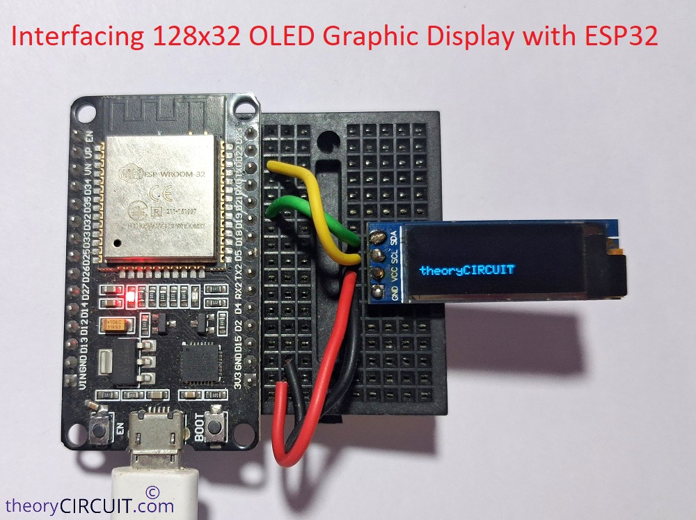
  display.println("128x32 Display"); */ // These two lines are not displayed on my OLED display. I think I damaged it while soldering the pins!

  display.setCursor(0,24);
  display.println("theoryCIRCUIT");

  display.display();
}

void loop()
{

}
Step 4: Display Your Running Text
Here is the simple code to display your running text
#include <Wire.h>
#include <Adafruit_GFX.h>
#include <Adafruit_SSD1306.h>

#define SCREEN_WIDTH 128
#define SCREEN_HEIGHT 32
#define OLED_RESET -1

Adafruit_SSD1306 display(SCREEN_WIDTH, SCREEN_HEIGHT, &Wire, OLED_RESET);

// Scrolling text
String scrollText = "128X32 Display - theoryCIRCUIT";
int xPos = SCREEN_WIDTH;

void setup()
{
  Serial.begin(115200);

  // Initialize I2C (ESP32 default pins: SDA = 21, SCL = 22)
  Wire.begin(21, 22);

  // Initialize OLED
  if (!display.begin(SSD1306_SWITCHCAPVCC, 0x3C))
  {
    Serial.println("SSD1306 allocation failed");
    while (true);
  }

  display.clearDisplay();
  display.setTextColor(SSD1306_WHITE);
}

void loop()
{
  display.clearDisplay();

   // Scrolling text
  display.setCursor(xPos, 24);
  display.print(scrollText);

  display.display();

  // Calculate text width automatically
  int16_t x1, y1;
  uint16_t w, h;
  display.getTextBounds(scrollText, 0, 24, &x1, &y1, &w, &h);

  xPos--;

  // Restart scrolling when text completely disappears
  if (xPos < -w)
  {
    xPos = SCREEN_WIDTH;
  }

  delay(15);   // Lower value = faster scrolling
}
That’s it, you can use this low power consuming display to draw sharp graphics, running texts, message text display, for wearable projects, tiny sensor data display etc.,