
Last Updated on March 16, 2024
As electronics enthusiasts and professionals, we often find ourselves immersed in the soldering process, creating intricate circuits and bringing our electronic dreams to life. However, one aspect that is sometimes overlooked is the smoke produced during soldering process. Here is the importance of a simple soldering smoke extractor circuit and why we need to build one.
Why Do We Need a Soldering Smoke Extractor?
We often repeat ourselves “Safety First”, So the Health Concerns is first one reason for building solder smoke extractor, Soldering involves the melting of solder, which emits fumes that can contain harmful substances like lead and flux. Prolonged exposure to these fumes can pose health risks, especially when working in enclosed spaces. A soldering smoke extractor ensures a healthier workspace by effectively removing these harmful fumes from the soldering iron.
Second thing is Enhanced Visibility, Excessive smoke can obstruct your view of the soldering area, making it challenging to achieve precision and accuracy. A smoke extractor helps maintain a clear line of sight, ensuring that you can work with ease and produce high quality solder joints.
Third thing is Longer Equipment Lifespan, Soldering smoke not only affects your health but can also harm your soldering equipment over time. Residue from the fumes may settle on sensitive electronic components, leading to corrosion and reduced lifespan. A smoke extractor plays a crucial role in preventing such issues and preserving the longevity of your tools.
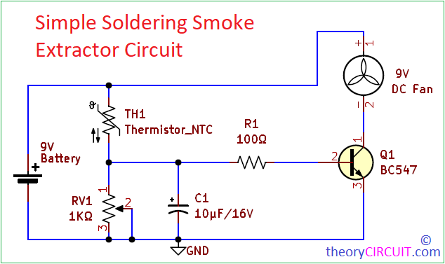
Circuit Diagram
Components List
- NTC Thermistor 10K
- Variable Resistor 1KΩ
- Resistor 100Ω
- Capacitor 10μF/16V
- Transistor BC547
- DC Fan (5V or 9V)
- Battery 9V
Construction & Working
Construction of this soldering smoke extractor circuit is simple and easy, Here the NTC Thermistor component must be placed close to the soldering iron tip attached with stand. Variable Resistor RV1 varies the sensitivity level. We know the Negative Temperature Coefficient Thermistor gives 10KΩ Maximum Resistance value when there is no external heat, when it sense temperature then the Resistance value will decrease depends on the temperature level. This Voltage divider setup makes it possible to sense the variation in voltage caused by variation in resistance of Thermistor. You can also use a fixed value resistor in place of Variable resistor VR1 for a fix triggering point, but this will require some calculations…,
Output from the voltage divider is connected to the Transistor base through Resistor R1 and C1, Here C1 ensures smooth voltage increase and decrease. When the Transistor Q1 Base gets above 0.7V, it starts to conduct and makes flow of ground supply to the fan, depends on the Base Voltage Conductivity between Collector and Emitter increase and maximize the fan speed. By the way smoke from the Soldering Iron extracted, place the fan backside (Air Suctions Side Facing Soldering Iron) and use sponge in front side of fan to trap smoke.
Very very good thank you