Last Updated on March 16, 2024
Measuring temperature can be done in two ways they are 1. contact method. 2. Non contact method, here many semiconductor based temperature sensors are available, For Non contact method temperature sensing few notable sensors only available in the market. mlx90614 is a very famous non contact IR Thermometer sensor in TO-39 package. mlx90614 Arduino code will give the exact temperature range in Fahrenheit and Celsius. mlx90614 sensor can work with any type of Arduino board. Here mlx90614 with Arduino Uno documented.
What is mlx90614?
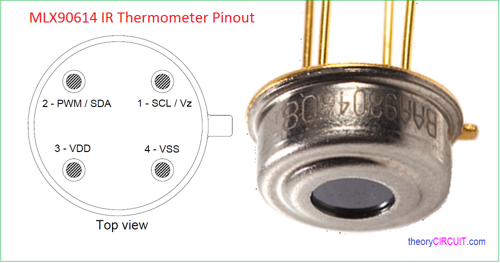
The mlx90614 is an Infra Red thermometer Sensor for non contact temperature measurements from melexis. mlx90614 sensor module contains IR Sensitive thermopile detector chip and the signal conditioning ASSP in same TO-39 package. It can measure -20° to 120° C without any interruption.
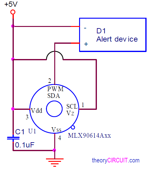
Function diagram of mlx90614
This circuit Represents standalone application and function diagram of mlx90614. Output (PWM) from mlx90614 is directly connected with the alert device. When the sensing temperature rises then the alert device will start work.
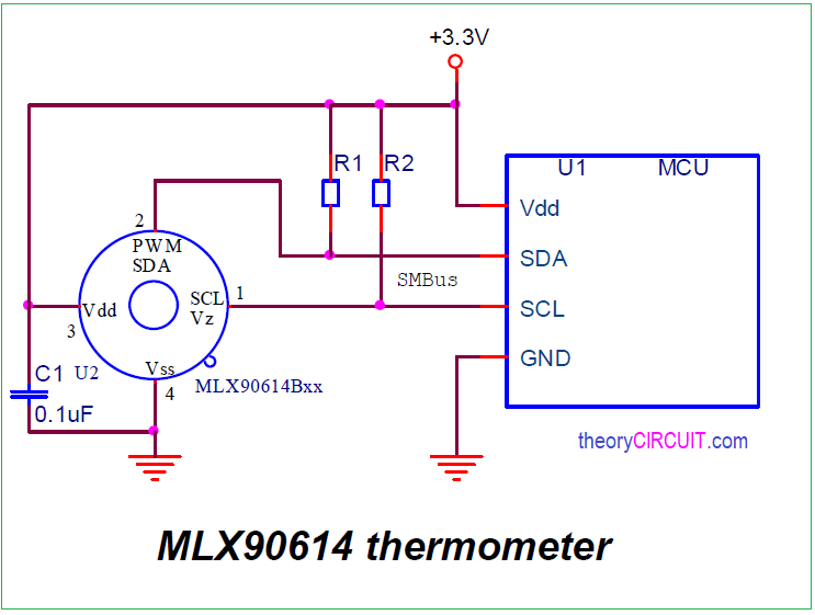
MLX90614 Sensor with Microcontroller
mlx90614 Infrared temperature sensor has I2C communication lines so that we can easily Interface it with any Microcontrollers which have I2C communication terminals in our case Arduino Uno I2C lines are SDA – A4 / SCL – A5 pins. Here the sensor operates in 3.3 volt DC supply, If the microcontroller operates in 5 volt DC then we need pull up Resistors between SDA amd SCL lines to +3.3 V DC line.
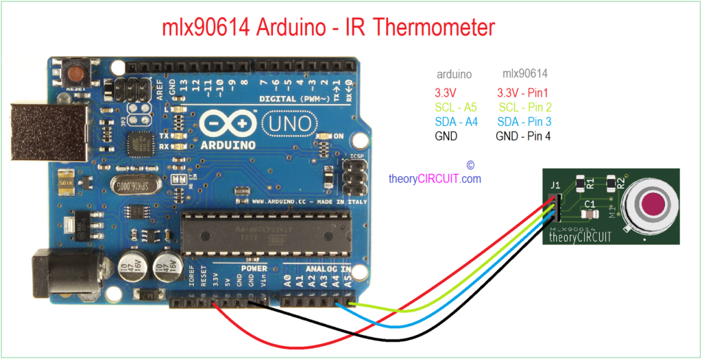
MLX90614 Arduino IR Thermometer
MLX90614 Arduino Wiring
Connect mlx90614 sensor breakout board and Arduino board as mentioned in diagram. (Note:- If you are using Arduino board other than Arduino Uno, then refer the SDA / SCL pins of your board and connect wisely. Wrong I2C connection will not give results ). mlx90614 Sensor breakout board pin 1 to 3.3 V, pin 2 to A5, pin 3 to A4 and pin 4 to GND of Arduino uno board.
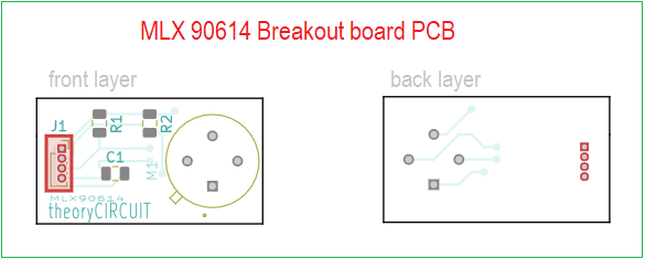
MLX90614 Sensor Breakout board PCB Files
Schematic Diagram of mlx90614
BOM
| s.no | References | Value | Footprint | Quantity | ||
| 1 | C1 | 0.1µF | C_0805_2012Metric | 1 | ||
| 2 | R1, R2 | 10KΩ | R_0805_2012Metric | 2 | ||
| 3 | M1 | MLX90614 | TO254P942H425-4 | 1 | ||
| 4 | J1 | PinSocket_1x04_P1.00mm_Vertical | 1 |
MLX90614 Sensor Breakout board Gerber File
MLX90614 Sensor Breakout Board Gerber File.
MLX90614 Sensor Board PCB Layout
Interactive Board Viewer
mlx90614 Arduino Code
/*************************************************** theoryCIRCUIT***********
  This is a library example for the MLX90614 Temp Sensor

  Designed specifically to work with the MLX90614 sensors in the
  adafruit shop
  ----> https://www.adafruit.com/products/1747 3V version
  ----> https://www.adafruit.com/products/1748 5V version

  These sensors use I2C to communicate, 2 pins are required to
  interface
  Adafruit invests time and resources providing this open source code,
  please support Adafruit and open-source hardware by purchasing
  products from Adafruit!

  Written by Limor Fried/Ladyada for Adafruit Industries.
  BSD license, all text above must be included in any redistribution
 ****************************************************/
 /*
  MLX90614 ------------- Arduino
  VDD ------------------ 3.3V
  VSS ------------------ GND
  SDA ------------------ SDA (A4)
  SCL ------------------ SCL (A5)
  */

#include <Wire.h>
#include <Adafruit_MLX90614.h>

Adafruit_MLX90614 mlx = Adafruit_MLX90614();

void setup() {
  Serial.begin(9600);

  Serial.println("Adafruit MLX90614 test");

  mlx.begin();
}

void loop() {
  Serial.print("Ambient = "); Serial.print(mlx.readAmbientTempC());
  Serial.print("*C\tObject = "); Serial.print(mlx.readObjectTempC()); Serial.println("*C");
  Serial.print("Ambient = "); Serial.print(mlx.readAmbientTempF());
  Serial.print("*F\tObject = "); Serial.print(mlx.readObjectTempF()); Serial.println("*F");

  Serial.println();
  delay(500);
}

