
Last Updated on March 29, 2024
To Produce Powerful Audio Sound we need good Power Amplifier, Here 100 Watt Transistor Audio Amplifier Circuit designed with power transistors section and high impedance pre-amplifier section. This circuit drives 12 inch 4Ω to 8Ω (ohm) 100 Watts Speaker. For convenient this amplifier circuit designed without amplitude control, you have to use limitation circuit for volume control before applying audio input to this circuit. To give better output and low noise this circuit is designed as a Class D power amplifier and Output stage transistors configured to give low impedance as possible to the load loud speaker.
Designing 100 Watt Transistor Audio Power Amplifier Circuit requires careful consideration of various factors to ensure optimal performance and reliability. When we need high output power then we have to apply high bias that is high input voltage. This circuit uses 35V Dual Power Supply (+35V, GND, -35V), choose the 36-0-36 Volt AC, 2A Stepdown transformer and Power Diodes to Rectify the AC to DC. Use strong DC filters and better to utilize Linear Voltage Regulator to Regulate DC power supply. Then apply that DC supply to this Amplifier for better performance.
Circuit Diagram
Components Required (BOM)
| 1 | C1 | 47μF/50V | CP_Radial_D13.0mm_P7.50mm | 1 | ||
| 2 | C2 | 560pF | C_Disc_D4.7mm_W2.5mm_P5.00mm | 1 | ||
| 3 | C3 | 10μF/50V | CP_Radial_D13.0mm_P7.50mm | 1 | ||
| 4 | C4 | 4.7μF/50V | CP_Radial_D13.0mm_P7.50mm | 1 | ||
| 5 | C5 | 1μF/50V | CP_Radial_D13.0mm_P7.50mm | 1 | ||
| 6 | R5, R7, R8 | 22Ω | R_Axial_DIN0414_L11.9mm_D4.5mm_P15.24mm_Horizontal | 3 | ||
| 7 | R1, R2 | 1Ω/5W | R_Axial_Power_L20.0mm_W6.4mm_P22.40mm | 2 | ||
| 8 | R3, R4 | 100Ω | R_Axial_DIN0414_L11.9mm_D4.5mm_P15.24mm_Horizontal | 2 | ||
| 9 | R6, R14 | 10KΩ | R_Axial_DIN0414_L11.9mm_D4.5mm_P15.24mm_Horizontal | 2 | ||
| 10 | R11, R16 | 47KΩ | R_Axial_DIN0414_L11.9mm_D4.5mm_P15.24mm_Horizontal | 2 | ||
| 11 | R12, R13 | 680Ω | R_Axial_DIN0414_L11.9mm_D4.5mm_P15.24mm_Horizontal | 2 | ||
| 12 | R9 | 1.5KΩ | R_Axial_DIN0414_L11.9mm_D4.5mm_P15.24mm_Horizontal | 1 | ||
| 13 | R10 | 1KΩ | R_Axial_DIN0414_L11.9mm_D4.5mm_P15.24mm_Horizontal | 1 | ||
| 14 | R15 | 4.7KΩ | R_Axial_DIN0414_L11.9mm_D4.5mm_P15.24mm_Horizontal | 1 | ||
| 15 | D1, D2 | 1N4007 | D_DO-41_SOD81_P10.16mm_Horizontal | 2 | ||
| 16 | Q1, Q2 | 2N3773 | TO-3 | 2 | ||
| 17 | Q3, Q5 | 2N6107 | TO-3P-3_Vertical | 2 | ||
| 18 | Q6, Q7 | BC108 | TO-5-3 | 2 | ||
| 19 | LS1 | Speaker | TerminalBlock_Dinkle_DT-55-B01X-02_P10.00mm | 1 | ||
| 20 | Q4 | 2N5294 | TO-3P-3_Vertical | 1 | ||
| 21 | J1 | Audio Input | TerminalBlock_Altech_AK300-2_P5.00mm | 1 | ||
| 22 | J2 | +35V | TerminalBlock_Altech_AK300-2_P5.00mm | 1 |
Construction & Working
As previously said this Power Amplifier circuit uses Two Transistors (Q6 and Q7) as a preamplifier then Q1, Q2 and Q3, Q4 transistors are acts as a power output stage transistors. Transistor Q5 couples both Preamplifier section and power output stage. When we apply Audio Signal through terminal block J1, Preamplifier amplifies the audio signal suitable for power stage, This section operates in its linear region and does not clip input audio signal. Signal Strength and phase angle correction done by the transistor Q5 and gives output signal to Transistor Q4 and Q3. Both NPN and PNP transistors ensures the amplification of Positive and negative clips in audio signal.
Transistor Q1 and Q2 delivers high Amplified Audio signal to the loud speaker through Audio output terminal block. Use proper heatsink and Quality cabinet for amplifier board. Refer the following Pinout details For better understanding of each transistor used in this circuit.
Transistor BC108 Pinout
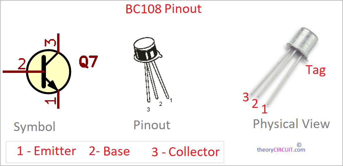
BC108 is NPN Silicon Planar Epitaxial Transistors and General Purpose Amplifier Transistor. Main features of this BC108 Transistor are, it can give maximum collector current (Ic) around 100 mA and Maximum collector Emitter Voltage (Vce) around 25V. This transistor can give around 300 mW Maximum power dissipation. BC108 comes in TO-18 metal can package and it can handle -65°C to +150°C Temperature. This is very good range for audio amplifier circuit.
Transistor 2N5294 Pinout
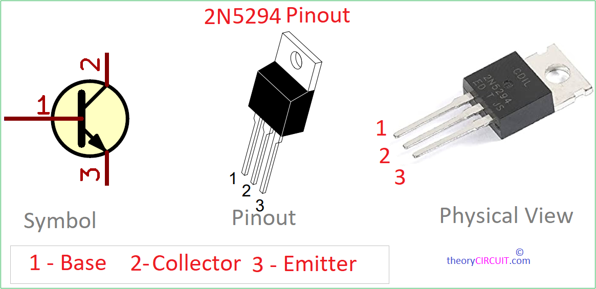
Transistor 2N5294 is a NPN Silicon Planar Epitaxial Transistor, This is good option for audio amplification available in the market. This transistor offers a maximum collector current (Ic) rating of approximately 15 amperes (15 Amps), making it suitable for high-power audio applications. It can handle a maximum collector-emitter voltage (Vce) of around 60 volts, allowing for significant voltage levels in various circuits. With a maximum power dissipation (Pd) of about 150 watts, Transistor 2N5294 demonstrates excellent thermal performance and reliability under high-power conditions. This transistor operates within a wide temperature range, from -65°C to +150°C. This transistor comes in TO-3 metal can package. Due to its high current and voltage ratings make this transistor particularly suitable for audio amplifier circuits, and audio systems.
Transistor 2N6107 Pinout
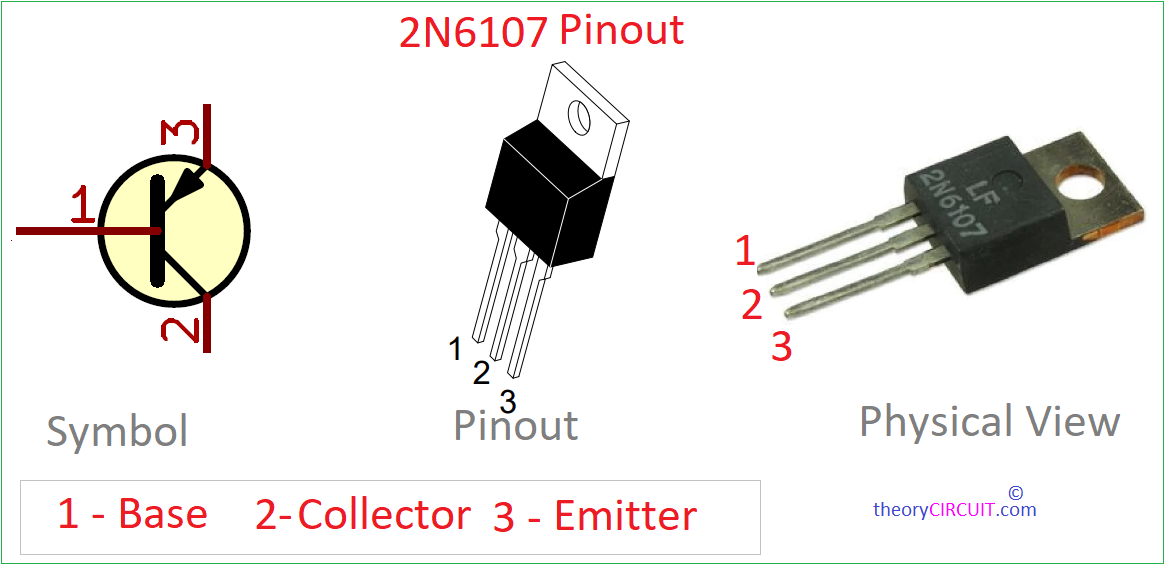
Transistor 2N6107 is a PNP Silicon Planar Epitaxial Transistor designed for high-power Audio applications. This transistor can handle maximum collector current (Ic) upto 16 amperes (16 Amps), With a maximum collector-emitter voltage (Vce) of around 200 volts. Its maximum power dissipation (Pd) is typically around 150 watts, indicating its ability to handle significant power levels while maintaining stability. Operating within a wide temperature range, from -65°C to +150°C. 2N6107 comes in TO-220 metal can package, the 2N6107 is commonly used in power amplification circuits.
Transistor 2N3773 Pinout
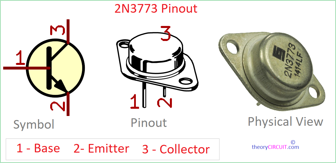
Transistor 2N3773 is a high power NPN Silicon Epitaxial-Base Planar Transistor. This transistor is designed for High Power Audio Output stage, With a maximum collector current (Ic) up to 16 amperes (16 Amps), and maximum collector-emitter voltage (Vce) of around 160 volts. Transistor 2N3773 have maximum power dissipation (Pd) of about 150 watts. Operating within a wide temperature range from -65°C to +200°C. 2N3773 Comes in TO−3 metal can package, the 2N3773 is commonly utilized in power amplifiers, audio amplification systems.
Printed Circuit Board
100 Watt Transistor Audio Power Amplifier Circuit PCB Gerber Files.
Interactive Board Viewer


100 Watt Transistor Audio Power Amplifier Circuit PCB 3D View
PCB Size and tracks are depends on the component size, Measure every components size and footprints before making PCB.
Thank you
for posting this cct. Can you use for real application, like public addressing system?