Last Updated on March 16, 2024
Some application projects need supply after some time delay or need to cut the supply after some delay for that purpose we can use this simple time delay relay circuit.
Time delay relay circuit contains a electromechanical relay and driver circuit, this circuit decides the time delay to give power supply to the electromechanical relay coil by the way to the load connected to the relay.
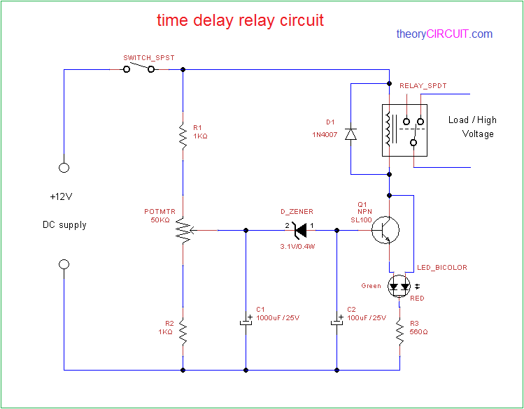
Circuit Diagram
Construction & Working
First section of this circuit is time delay elements such as voltage divider resistor series and two electrolytic capacitor and Second section is Relay with indicator LED.
Resistor R1, potentiometer and R2 connected in series and across to the DC input supply, output of variable resistor (potentiometer) is connected to the C1 capacitor and reverse biased Zener diode then C2 capacitor finally to the base of transistor SL100.
12V Relay is connected with the collector terminal of SL100 transistor and Bicolor LED terminal green is connected with emitter of Q1 and terminal Red is connected across collector.
When the supply given to this circuit depends on the value of Potentiometer small level voltage passed to C1 and it gets charged when its completed and above the cutoff limit of zener diode, Voltage passed to C2 capacitor and it gets charge, finally the base emitter voltage limit of Q1 transistor reched by the C2 then Q1 gets turn ON and Relay coil gets complete DC supply then Relay energised for to complete the above process it takes some time delay depends on Potentiometer value, C1-C2 charge time and Zenerdiode breakdown voltage hence we can achieve few seconds to few minutes time delay.
By changing the Potentiometer value or C1-C2 value we can achieve different time delay levels. We can use this circuit to turn ON or turn OFF some sensitive time delay required electrical applications.
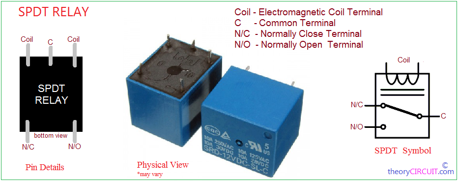
Relay