Last Updated on March 16, 2024
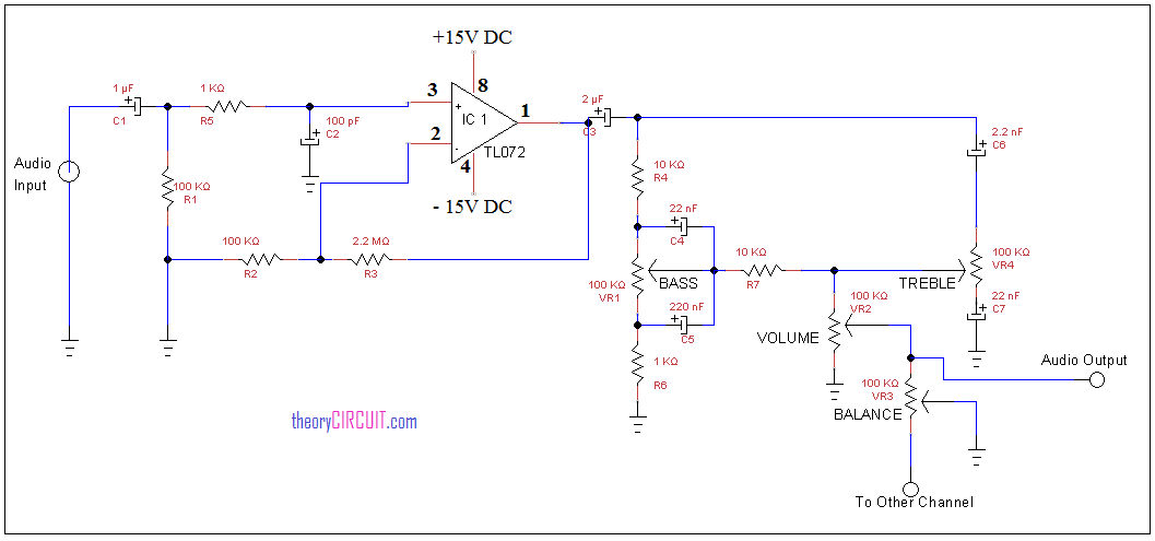
This tone control circuit is constructed by using low noise JFET input operational amplifier TL072 integrated circuit, this operational amplifier gives low noise output with few external components, it needs +ve and -Ve dual bias supply for better operation.
Circuit diagram for tone control
Construction and Working
Audio input signal is applied to the operational amplifier with balanced circuit, here resistor R3 and R2 elements are acts as feed back for amplifier, output from the amplifier is applied to the tone control circuit, the tone control circuit controls bass, treble and balance effects in the output audio signal, output to the speaker is taken from volume control variable resistor VR2, balance control VR3 gives signal extension for other channel amplification.
Dual power supply for operational amplifier

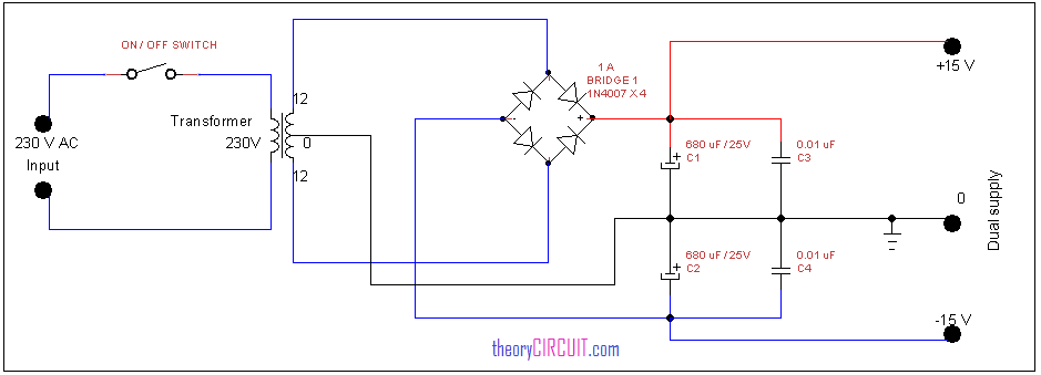
The operational amplifier TL072 and some amplifiers are needs dual power supply for perfect amplification, hence here we given simple few components dual supply circuit, this is constructed by using step down transformer (12-0-12 V) center tapped output, 1 Amps bridge rectifier for AC to DC conversion and filtering capacitors, from this circuit we can get +15V-0- -15V dual supply.
![]()
Datasheet of IC TL072

