
Last Updated on March 16, 2024
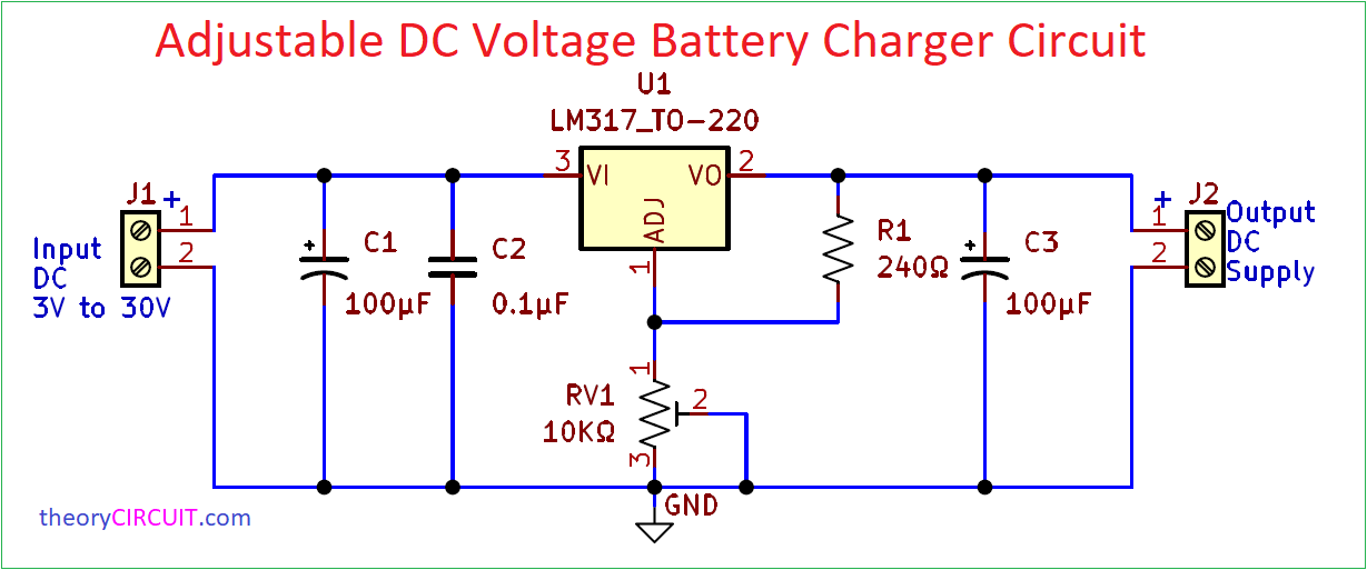
Easy to Construct Adjustable DC Voltage Battery Charger Circuit is designed by using Three Terminal Adustable Voltage Regulator IC LM317 from Texas Instruments. The LM317 component serves as an adaptable three-terminal voltage regulator with a positive polarity, capable of delivering a current exceeding 1.5 A. It operates across a versatile output voltage spectrum, ranging from 1.25 V to 37 V. The configuration necessitates only two external resistors for configuring the desired output voltage.
IC LM317 exhibits noteworthy characteristics, boasting a typical line regulation of 0.01% and a typical load regulation of 0.1%. Furthermore, it encompasses essential protective mechanisms such as current limiting and safe operating area protection. Overload protection remains functional even if the ADJUST terminal is disconnected.
Circuit Diagram
Components Required
| 1 | C1, C3 | 100μF | CP_Radial_D4.0mm_P1.50mm | 2 | ||
| 2 | C2 | 0.1μF | C_Disc_D3.0mm_W1.6mm_P2.50mm | 1 | ||
| 3 | R1 | 240Ω | R_Axial_DIN0207_L6.3mm_D2.5mm_P7.62mm_Horizontal | 1 | ||
| 4 | U1 | LM317_TO-220 | TO-220-3_Vertical | 1 | ||
| 5 | RV1 | 10KΩ | Potentiometer_Bourns_3266W_Vertical | 1 | ||
| 6 | J1, J2 | Screw_Terminal_01x02 | TerminalBlock_Altech_AK300-2_P5.00mm | 2 |
Construction & Working
To keep it very simple and easy to use with all kind of discrete batteries this Adjustable DC Voltage regulator constructed with few Filtering Capacitors (C1, C2 – input and C3 – Output), Variable Resistor RV1 for Adusting output Voltage. As we know The LM317 is a widely utilized integrated circuit in electronics, functions as an adjustable voltage regulator with notable flexibility. Starting with the acceptance of an unregulated DC input voltage, typically derived from a rectified and filtered AC power source. This input voltage spans from slightly above the desired output voltage to a maximum of approximately 37 volts. Precise control over the output voltage is achieved through external components, specifically two resistors, R1 and R2 (here RV1) , connected to the ADJUST (ADJ) and OUTPUT (OUT) pins.
VOUT = 1.25V × (1 + (R2 / R1))
The LM317 uses a reference voltage of 1.25 volts bridging the ADJUST and OUTPUT pins, serving as a baseline for voltage regulation. It employs a feedback mechanism that continuously compares this reference voltage to a fraction of the output voltage, ensuring stable and accurate regulation. Furthermore, built-in features such as current limiting and thermal overload protection safeguard both the IC and the connected load. This combination of versatility and protective mechanisms has made the LM317 a cornerstone in applications requiring precise and adjustable voltage regulation.
Printed Circuit Board
Adjustable DC Voltage Battery Charger Circuit PCB Gerber Files.
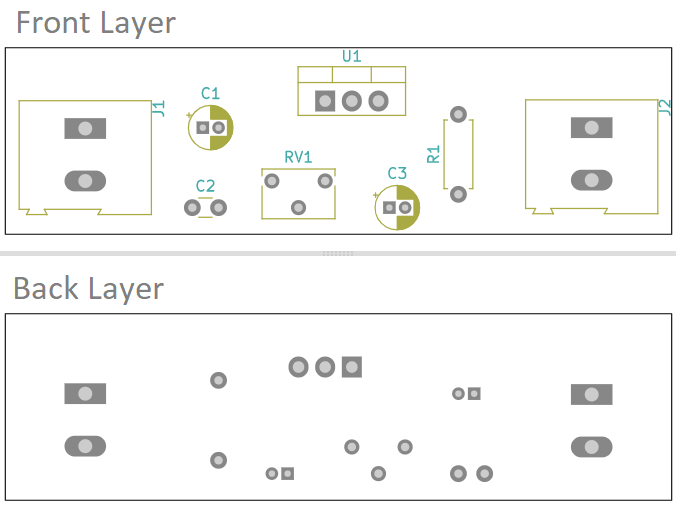
Interactive Board Viewer


Can u give simulation of this circuit in kikad