
Last Updated on April 26, 2024
We always want to build LED Flasher circuit for home decoration or for warning sign or for some other indication applications and we mostly end up with IC based circuits or Microcontroller based circuit. Here is the cost effective and reliable solution, Simple and easy to build LED Flasher Circuit using BC547 Transistor. Resistor and Capacitor are acting as timing element and the transistor act as switch to make charge and discharge in the capacitor.
This Transistor based Astable Multivibrator constantly produce two different Square wave sequence at output (Collector Terminal). So the connected LEDs ON and OFF for High and Low Pulses makes flashing effect.
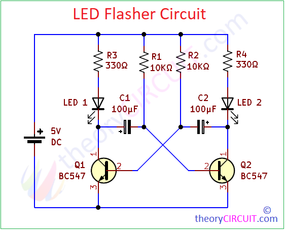
Circuit Diagram
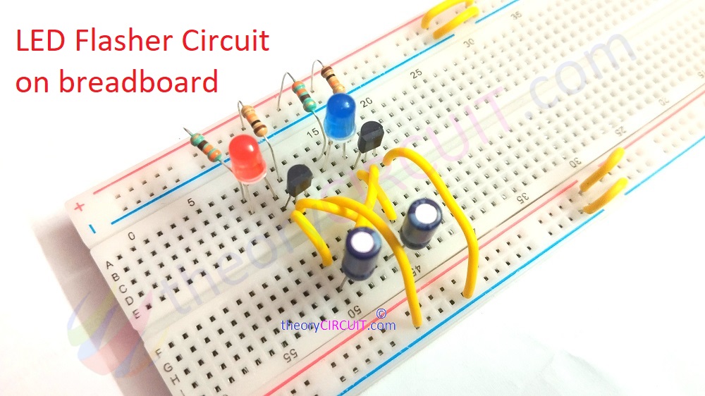
LED Flasher Circuit in Action
Components List
- Transistor BC547(NPN) = 2
- Electrolytic Capacitor 100μF = 2
- Electrolytic Capacitor 10μF = 2
- LED = 2 (different color)
- Resistor 10KΩ = 2
- Resistor 330Ω = 2
- Breadboard
- Connecting Wires
- DC power Supply (5 Volt)
Construction & Working
This LED Flasher Circuit or Blinking circuit constructed by two cross coupled transistors, it can be either NPN or PNP, here we have used two BC547 transistors. If you want to produce high frequency output then use high switching speed transistor in this circuit. Here both BC547 transistors are biased as common emitter amplifier with 100% Positive feedback, both transistor base terminal is connected with timing element Resistor and Capacitor junction. (Remember Two set of Resistor and Capacitor for timing element should have same Values – tolerance negligible). Two LEDs are connected at the collector terminal through current limiting Resistors.
This connection satisfies the condition for Oscillation, so any one Transistor (Which one is receives quick bias) starts conducting in saturation condition which is termed as “ON” and other transistor (Which one is re8ceives late bias) stays in “OFF” that is Cut-off stage. This leads to mutual amplification between two transistors (Q1 and Q2) and ‘ON’ stage is transferred to ‘OFF’ through discharging capacitor and ‘OFF’ stage is transferred to ‘ON’ stage by charging capacitor. So that LEDs connected at the collector terminals starts flashing.
Here is method to calculate the frequency of oscillation in this free running circuit. There is no external trigger is required for pulse oscillation so that it is called as free running circuit.
T = t1 + t2
t1 = 0.69C1R1
t2 = 0.69C2R2
f = 1/T = 1/1.38RC
Remember to use same value timing components, R1 = R2 and C1 = C2.
Here we used 10KΩ Resistor and 100μF Capacitor (set 1 experiment) and 10μF Capacitor (set 2 experiment), So the output frequency is,
f = 1/T = 1/1.38RC
f = 1/1.38*10000Ω*0.0001F
f = 1/1.38 sec
f = 0.72 Hz (slow flashing)
When we use 10μF Capacitor for C1 and C2,
f = 1/T = 1/1.38RC
f = 1/1.38*10000Ω*0.00001F
f = 1/0.0724 sec
f = 13.8 Hz (fast flashing)
Hi is it possible for you to explain the same circuit on a Vero board? I have a project coming up for it
Hi Babar
Explanation for this circuit in bread board, Vero board or any other board is same. You have to make proper soldering, if you want to build this circuit on Vero board.
For the 10uF capacitor, I think f should be 7.4Hz.
Sorry, I should say: f should be 7.24Hz.