
Last Updated on March 22, 2026
Motion detection when you hear it, It sounds fancy. But honestly it’s one of the simplest things you can do as a standalone or microcontroller based projects by using the HC-SR501 PIR Motion detector sensor, It detects IR changes and gives output through single pin. You just read a single pin. That’s it, Here is the simple way to interface HC-SR501 with ESP32 and basic code.
What Is the HC-SR501?
Passive Infrared motion Sensor module product name is HC-SR501. It detect motion by sensing changes in Infrared Radiation which is basically body heat or object with above room temperature and it can not detect cold objects (you know that, cold objects don’t emit ir), HC SR501 is passive sensor because this sensor depends on the source for signal.
HC SR501 PIR sensor module built with signal processing circuit based on BISS0001 IC, it gives output through single pin either HIGH or LOW based on the tiny pyroelectric signal.
HC SR501 has three main parts,
• Fresnel lens dome – focuses IR radiation onto the sensor
• Dual-element pyroelectric sensor – detects the change in IR levels
• IC – the brain. Amplifies, compares, and outputs the signal.
HC SR501 has only three pins,
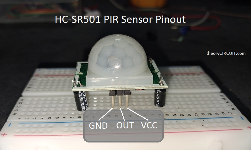
- VCC – (+5V to +12V)
- OUT – Signal output, Goes HIGH when motion is detected. LOW when no motion. You can change it by using trigger mode jumper.
- GND – Ground supply.
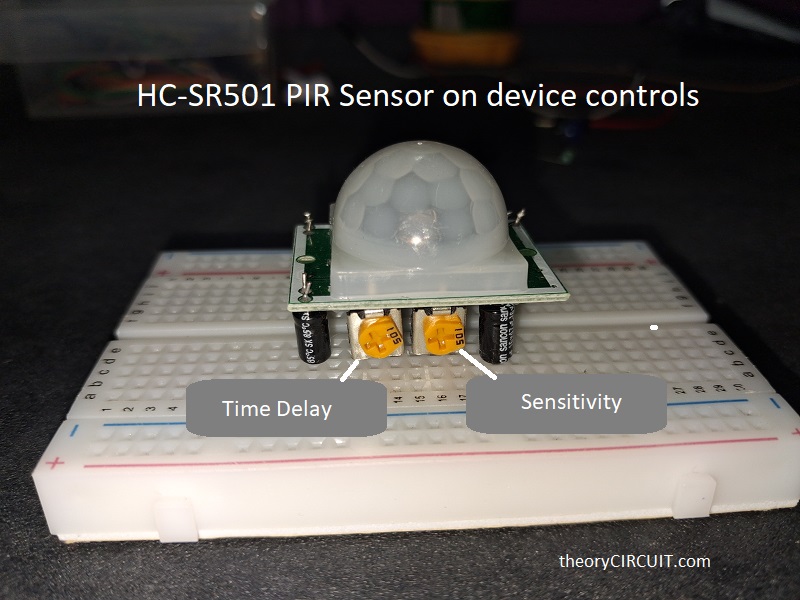
You may see two potentiometers at the back of the HC SR501 board. The time delay pot sets how long the OUT pin stays HIGH after motion is detected. (3 seconds to 5 minutes). Sensitivity pot makes changes in detection range. (maximum range 7 meters). Set both pots at the middle position to get started and then adjust based on your application.
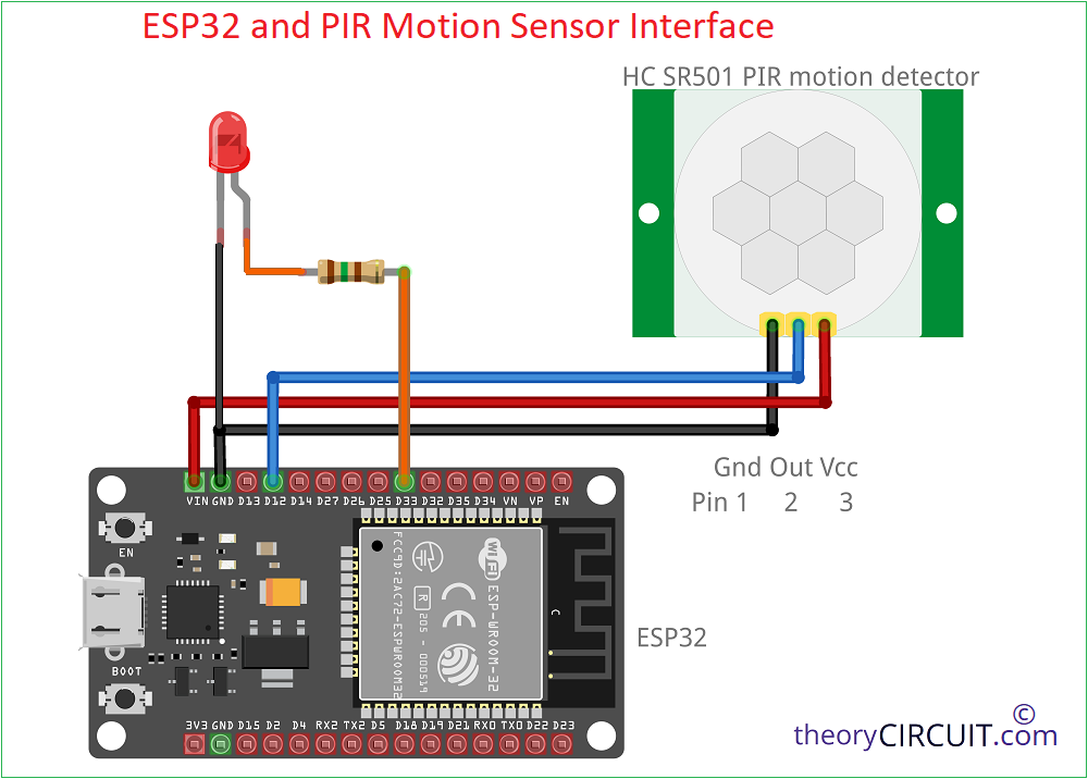
Interface Diagram
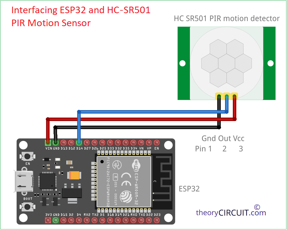
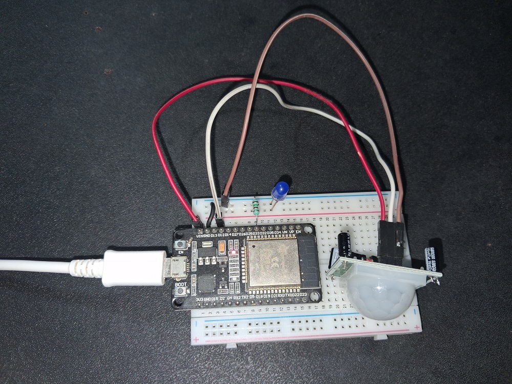
ESP32 HC-SR501 sensor and LED
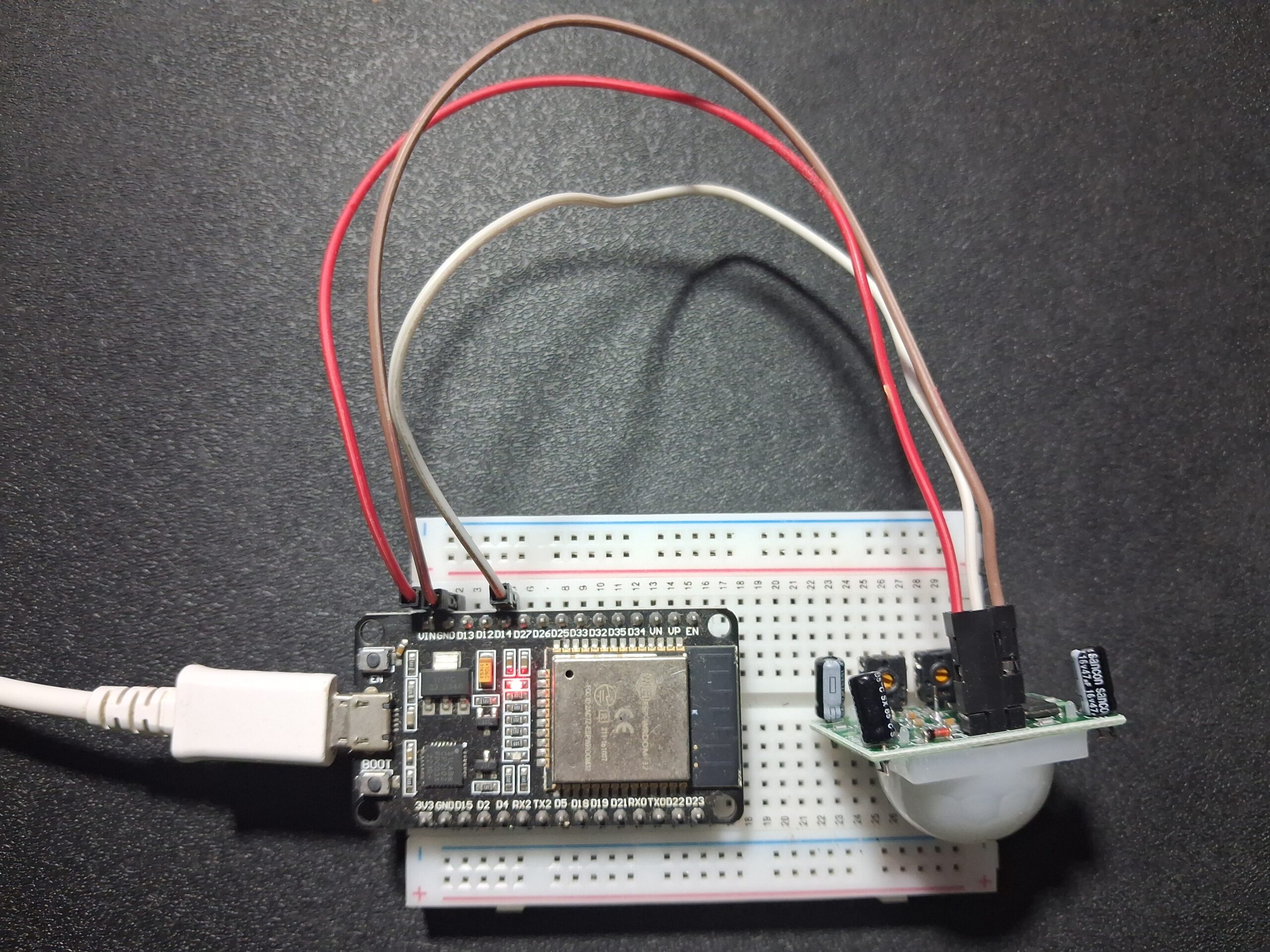
Components Required
- ESP32 Development board (Here we used ESP32 DOIT DevKit V1)
- PIR Motion Sensor (HC SR501)
- LED
- 150Ω Resistor
- Connecing wires
Wiring Notes
• Use VIN (not 3.3V) for the HC-SR501. The sensor needs 5V minimum. 3.3V will give unreliable results.
• The OUT pin outputs 3.3V HIGH signal – directly compatible with ESP32 GPIO. No level shifter needed.
• Keep wires short. Long signal wires can pick up noise.
• GPIO 14 is used in this example for basic setup and GPIO 12 for LED Test. You can use any digital GPIO on the ESP32.
Here the sensor HC-SR501 needs at least 30 second warm up time when first powered on. So don’t skip this in your code. It will trigger false positives otherwise.
Arduino IDE Code (Basic Interface)
// HC-SR501 + ESP32 | theorycircuit.com
#define PIR_PIN 14

void setup() {
  Serial.begin(115200);
  pinMode(PIR_PIN, INPUT);
  Serial.println("HC-SR501 Ready. Warming up...");
  delay(30000); // 30 sec warm-up — don't remove this
}

void loop() {
  int motionState = digitalRead(PIR_PIN);

  if (motionState == HIGH) {
    Serial.println("Motion Detected!");
    // Your action here: LED on, buzzer, MQTT publish
  } else {
    Serial.println("No Motion.");
  }
delay(500);
}
Arduino Code for motion detection test with LED
#define PIR_PIN   12    // PIR OUT → GPIO12 (as per your diagram)
#define LED_PIN   33    // LED → GPIO33

void setup() {
  Serial.begin(115200);

  pinMode(PIR_PIN, INPUT);
  pinMode(LED_PIN, OUTPUT);

  Serial.println("=================================");
  Serial.println(" ESP32 + PIR Motion Sensor ");
  Serial.println("=================================");
  Serial.println("Warming up sensor... (30 sec)");

  // PIR warm-up time
  for (int i = 30; i > 0; i--) {
    Serial.print("Ready in: ");
    Serial.print(i);
    Serial.println("s");
    delay(1000);
  }

  Serial.println("Sensor ready! Monitoring...");
  Serial.println("---------------------------------");
}

void loop() {
  int pirState = digitalRead(PIR_PIN);

  if (pirState == HIGH) {
    Serial.println(">> MOTION DETECTED!");
    digitalWrite(LED_PIN, HIGH);   // Turn ON LED
  }
  else {
    Serial.println("   No motion.");
    digitalWrite(LED_PIN, LOW);    // Turn OFF LED
  }

  delay(500);
}
Trigger Modes – H and L Jumper, For home automation and motion-activated lights, use H mode. It gives you continuous detection.