
Last Updated on March 16, 2024
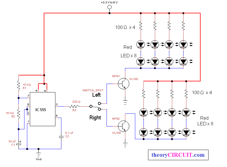
The Simple and useful bicycle direction indicator circuit is given, the Astable multivibrator is designed with IC 555 and the output is given to single pole dual through switch (spdt), the output fed into LEDs.
Hence it will glow frequently to indicate the turning direction (use yellow or orange colour LEDs), in this circuit you can choose Resistor R2 as a variable resistor to vary the speed of light.
Circuit diagram
Components List
| S.No | Name | Quantity |
| 1. | IC 555 | 1 |
| 2. | Transistor SL 100 | 2 |
| 3. | LED (yellow or orange colour) | 16 |
| 4. | SPDT switch | 1 |
| 5. | Resistor 100Ω 10KΩ 220Ω |
8 2 1 |
| 6. | Capacitor 33µF/16v ,0.1 µF | each 1 |