Last Updated on March 16, 2024
Here we present a circuit to control any home appliances through IR remote control, you can use any IR remote to control this circuit, by using this circuit we can turn on/off any device.
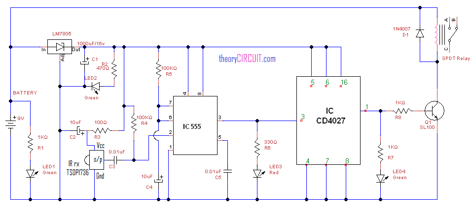
Circuit Diagram
Construction & Working details
The timer IC555 and Decade counter IC CD4027 are the main part of this circuit. The IR sensor TSOP1736 used to receive IR rays from remote control, the SPDT relay act as a electro-mechanical switch to make close and open the load circuit with power supply.
This circuit operated by using 9V DC supply, this supply is directly given to the relay and in other way regulated as 5V by using positive regulator IC 7805. The regulated 5V supply given to the timer IC and counter IC, when the IR rays fall on the sensor (TSOP1736) it will produce spike signal at 36KHz, this signal act as a trigger signal for timer IC, by this trigger input timer IC will produce pulse output at the pin3.
This pulse duration and duty cycle can be varied by varying R5 and C4 components. The output pulse from timer IC should be least 1 second duration. This pulse output is given to the decade counter hence the counter IC produce set output at pin1 this will turn on the Q1 transistor hence relay connects load to power supply.
If the IR rays received by IR sensor during the counter output as Set condition the above all operation continues but the counter output turned to Reset hence the transistor Q1 turns off so the relay disconnects load from power supply.
Get datasheet of IC CD4027/26 here…
Get datasheet of TSOP1736 here…
Get datasheet of SL100 here…