
Last Updated on March 24, 2024
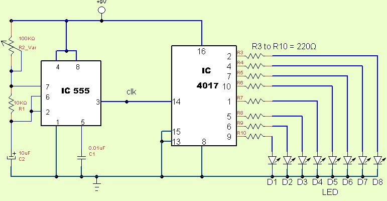
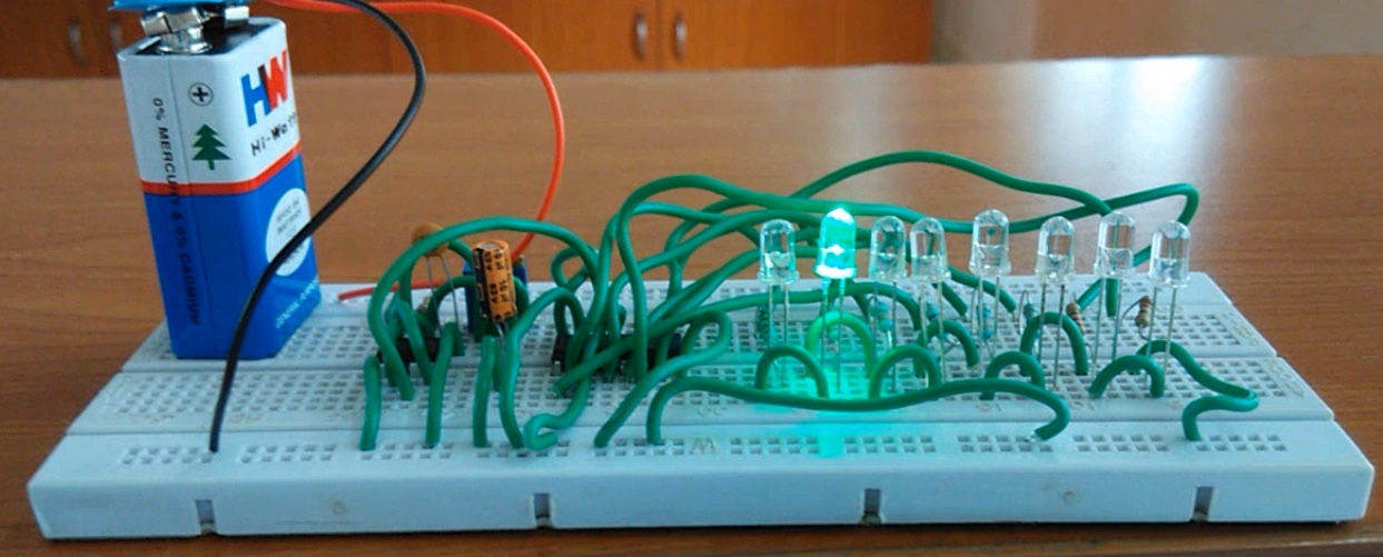
Built your own Running light chaser circuit, This running light chaser circuit consist of IC555 timer and IC4017 decade counter, This IC CD4017 drives up to 10 LEDs. Speed of glowing LED can be controlled by variable resistor in timer (IC 555) which is setting frequency output of timing pulse.
Circuit Diagram
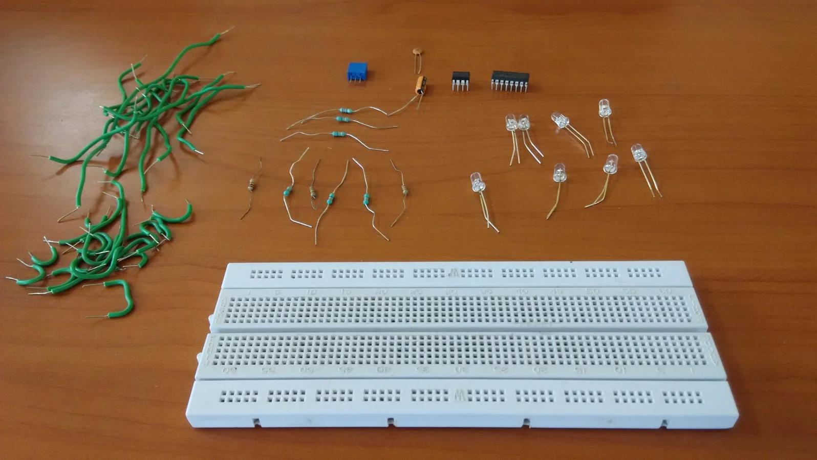
Components List
| S.No | Name | Quantity |
| 1. | IC 555 IC CD4017 | 1 1 |
| 2. | LED | 8 |
| 3. | Resistor 220Ω Resistor 10KΩ Variable Resistor 100KΩ | 8 1 1 |
| 4. | Capacitor 10uF Capacitor 0.01uF | 1 1 |
This circuit has three stages, the first one is pulse generator here we use timer (IC555) circuit to produce astable pulses. The second stage is decade counter (CD4017) this will count the astable pulse in a circle pattern. Final section is output LEDs, here we can connect different color LEDs to make the output beautiful.
Another Version
New LED Chaser Circuit Version