
Last Updated on March 16, 2024
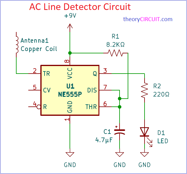
A Simple noncontact AC Line Detector Circuit is designed by using famous timer IC 555, This circuit uses a coil to detect tiny electromagnetic field and triggers the timer IC 555 to produce timing pulse at output. Connected LED will blink if the coil detects electromagnetic field around AC supply flowing cable. If the LED stays OFF then you have to check the continuity of the cable. This circuit can be used as Wireless Tester AC Line Detector without touching the wire.
Note:- This circuit involves in handling of High Volt AC working with electricity can be lethal, Do Not Touch AC Line Cable even if it is Insulated Handle with Extreme Care.
This circuit can be used to detect ac supply cable that placed inside a wall, for that you need to precheck and calibrate the circuit. More Number of turns in the Antenna Coil detects tiny amount of electromagnet around AC supply flowing Cable.
Circuit Diagram
Components Required
| 1 | C1 | 4.7μF | CP_Radial_D4.0mm_P1.50mm | 1 | ||
| 2 | R1 | 8.2KΩ | R_Axial_DIN0207_L6.3mm_D2.5mm_P7.62mm_Horizontal | 1 | ||
| 3 | R2 | 220Ω | R_Axial_DIN0207_L6.3mm_D2.5mm_P7.62mm_Horizontal | 1 | ||
| 4 | D1 | LED | LED_D5.0mm | 1 | ||
| 5 | U1 | NE555P | DIP-8_W7.62mm | 1 | ||
| 6 | Antenna1 | Copper Coil | PinHeader_1x02_P1.00mm_Vertical | 1 | ||
| 7 | BT1 | 9V | PinHeader_1x02_P2.00mm_Vertical | 1 |
Construction & Working
Here IC 555 configured in monostable multivibrator mode and the Reset Pin 4 is kept open, this will allow the timer IC to oscillate pulse whenever the trigger input appears at pin 2. Threshold and Discharge pins are connected with the timing capacitor C1 and positive supply applied to these pins through R1. Output Pin 3 is connected with LED through Resistor R2.
In this circuit, When the Coil attached with the trigger pin exposed to the electromagnetic field (Near AC Line Cable) then it will produce induced emf like sine Wave if that potential is above 1/3 VCC then the output of the timer will LOW and below 1/3 VCC then the output of timer will HIGH by the way LED glows for HIGH and gets off for LOW. This is how the AC Line Detector Circuit using Timer 555 works.
Printed Circuit Board
AC Line Detector Circuit PCB Gerber Files.
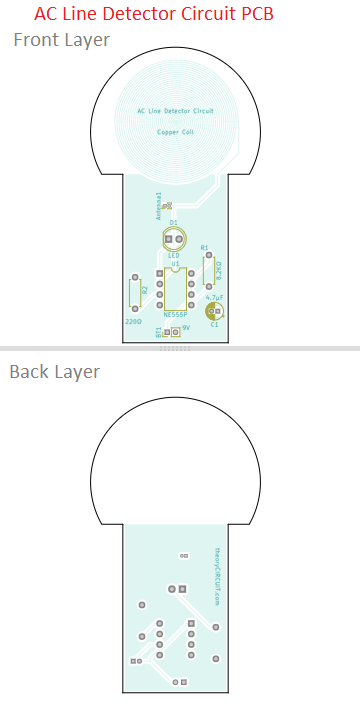
Interactive Board Viewer

