Last Updated on April 13, 2024
AC Power Motor Speed Control Circuit designed with SCR BRY44 acts as Single Phase AC Voltage Controller depends on the Gate Current and firing angle received in gate terminal through Variable Resistor called Var (500Ω/2W) and diode BAV21 (it is a general purpose PN Diode with 240V Voltage Rating).
Following Schematics are recommended for only professionals. And these circuit requires handling of High Voltage which may give Electric Shock!
Schematic is Obsolete and Updated Version available below.
Components List
| S.No | Name | Quantity |
| 1. | SCR BRY44 | 1 |
| 2. | Capacitor 2uF(220V) | 1 |
| 3. | Diode BAV21 | 1 |
| 4. | Resistor 1K Resistor 100R Variable Resistor 500R | 1 1 1 |
Here the AC Motor is connected to the Main power supply (Phase Terminal) through SCR BRY44 and Neutral to another contact of motor. So the motor gets AC supply phase only through SCR BRY44, but this SCR requires control signal that is Gate Current to get turn ON and conduct supply from Anode to Cathode, Here the Gate control supply is applied through Variable Resistor (500Ω/2W).
To Avoid back EMF from AC motor to Cathode terminal of SCR BRY44, a capacitor and Resistor used across Gate and motor phase contact connected cathode terminal. Here the ‘C’ helps to change the phase angle also. By varying Var.Resistor we get different level output voltage through SCR and so the AC motor speed got controlled.
(The Above Schematic is Obsolete and Not Recommended for new Designs.)
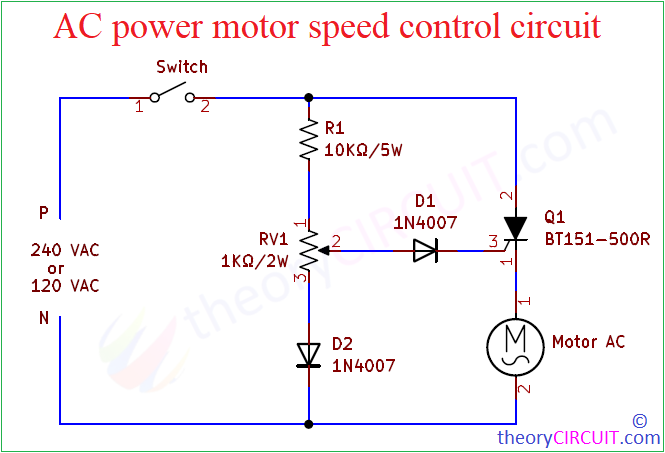
Updated Ac power motor speed control circuit Using SCR
List of Components
- SCR BT151-500R
- Diode 1N4007 = 2
- Resistor 10KΩ/5W
- Variable Resistor 1KΩ/2W
- AC Motor (series wound ac motor within 240V rating)
- SPST Switch
Before Jump into the construction and working details about this circuit, lets look into Special device BT151 SCR used in this circuit.
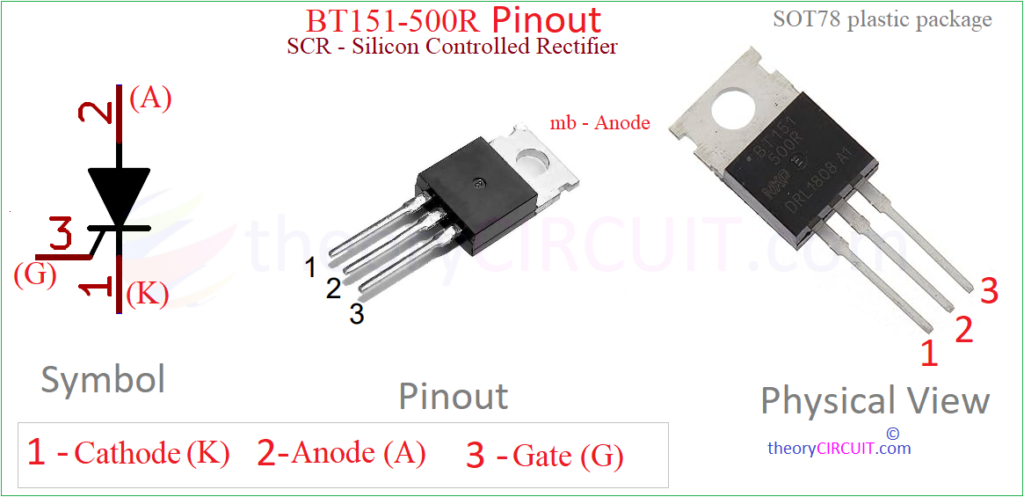
BT151 Pinout
Silicon Controlled Rectifier BT151-500R is a popular device which is specifically designed for medium power applications, with1`za voltage rating of 500V and a current rating of 12A. The BT151-500R comes in a SOT78 plastic package that can be termed as TO-220AB package, so that it can provide easy mounting and efficient heat dissipation through metal base. This SCR is widely used in various industrial and consumer electronic applications, including motor control, lighting control, power supplies, and heating systems. Refer datasheet for more to read.
This AC Motor Speed Control circuit is most suitable for Series Wound Electric Motors which can be Universal AC or DC electric motor. Back EMF produced by these type of motor is proportional to its speed. So the effective voltage will be Applied voltage subtracted with back EMF. Components connected to the Gate forms Phase delay circuit between Anode and Gate terminal of SCR BT151 and these components provides 90° of phase adjustment to the Gate and so the Motor Torque varied below this phase adjustment.


This is very similar to the circuit in the Dayton 4X701 motor speed control.
I tried to used for an old 220v ac motor for a polishing machine , but it has an ishue, the pot heats up more than anything and its a concern that it reaches 60 degrees before the scr reaches 30