
Last Updated on March 29, 2024
Now a days countless applications uses DC motors, to drive DC motor and to control direction of rotation we use different control circuits, in some situations we use microcontrollers. Here four different Simple Low Voltage DC Motor Speed Control Circuit designed by using few easily available components and without microcontrollers. These circuit will acts as standalone Speed control circuits. You can control the speed of a Brushed DC motor by varying the input voltage to it. When we apply Lower voltage we can slow down the motor (low RPM), while applying higher voltage Motor gets its High speed (High RPM). For some specific more accuracy RPM applications, we can use PWM (Pulse Width Modulation) in Speed control circuit.
Following Circuits are designed to drive low voltage and low power Brushed DC Motor. Keep in Mind that Minimum and Maximum RPM of motor is fixed and it can be increase or decrease by using gears.
Circuit Diagram
DC Motor Speed Control Circuit using MOSFET
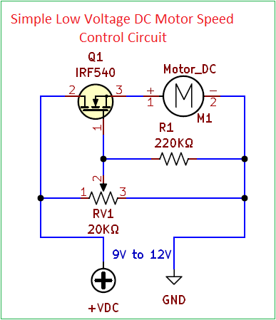
IRF540 Power MOSFET VI characteristics is used here to control the speed of DC motor, Positive bias terminal of motor is connected to the Source terminal of IRF540 and Negative terminal to Gnd. Drain pin of IRF540 is directly connected to the power supply positive pin. Gate terminal is connected to the variable pin of RV1. By varying the RV1 different level voltage will reach the gate terminal of IRF540. Depends on the Gate voltage, Current flow through the IRF540 (ID) changes and hence the voltage level to the DC motor change. Speed of DC motor will also change.
IRF540 MOSFET Pinout
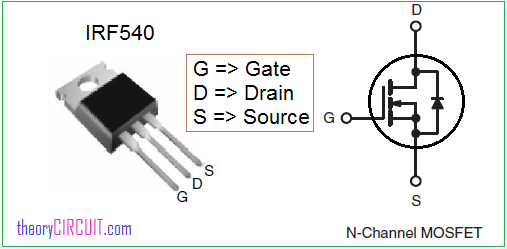
IRF540 is a N channel power MOSFET, Comes in TO-220 Package with three terminals. It can handle 100V drain-source voltage and continuous drain current of 33 A.
Low Voltage DC Motor Speed Control Circuit using TDA 7274
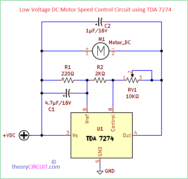
TDA 7274 is LOW-VOLTAGE DC MOTOR SPEED CONTROLLER Integrated circuit from STMicroelectronics. This IC have internal Voltage comparator and three transistor output stage. Inverting pin of comparator connected with internal 100μA current source and Non Inverting pin Acts as Control pin (8). Vref Pin (6) gives feed back to the internal comparator and Out pin (4) gives negative output voltage. DC motor Negative pin is connected to the Out pin of TDA 7274 by adjusting the RV1 Resistor we can change the output (Gnd Level) voltage by the way we can control the speed of DC motor.
“This IC used to control speed of motor in retro cassette player Now this is a Obsolete Product” Not Recommended for New Designs.
DC Motor Speed Control Circuit using IC 555

In this Circuit Timer IC 555 configured in Astable Multivibrator mode and biased to produce continuous square pulse output. Output pulse is connected to the high switching speed element IRF540 MOSFET. DC motor is connected between positive supply and Drain terminal of IRF540. Timer IC 555 Oscillates Square pulse By using the Timing Element VR1 and C2. Output pulse drives the MOSFET and changes its ON and OFF condition hence the motor gets discrete supply like cycle pedaling and speed of motor depends on the pulse ON time and OFF time. By varying the VR1 Value we can change the output pulse and also DC motor Speed.
DC Motor Speed Control PWM Circuit

In this circuit Timer IC 555 used to produce PWM (Pulse Width Modulation) signal and L293D quadruple high Current Half-H Driver to control the speed and rotating direction of DC Motor. Get more details about this Circuit here.
Timer IC 555 Pinout and Blocks
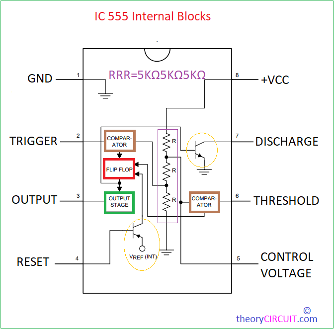
As we know this Timer IC 555 have two comparator, one flipflop, one output stage driver and three Resistor(5KΩ) Voltage Divider.