
Last Updated on May 1, 2024
This Circuit Involves in Handling of High Voltage AC Supply Handle With Extreme Care. Simple Arduino Power Inverter Circuit made with few Transistors and Step-down transformer, it is capable of delivering AC output supply from 200V to 230V by adjusting timing pulse output from the Arduino digital pins. We know Inverter circuits are very useful one to get High Voltage AC by using lower DC supply input from battery or any source.
Let’s look into few fundamental thing about electronic Inverter circuit, commonly Inverter is used to get High Voltage AC supply from low Voltage DC supply. Key components to design Inverter are,
- Input DC Supply Source
- Switching Circuit
- High Frequency Switching Pulse
- Transformer
Here the first thing is Input DC supply source either from battery (for standalone or solar based Inverter) or from adapter. Then we need switching circuit which can be made by power Transistor or power MOSFET, Condition for designing switching circuit requires fast enough and capable of handling High power, so in Arduino Inverter Circuit we used power transistor TIP31C.
For to generate High frequency switching pulse we used Arduino UNO board (you can use any Arduino board) and fetched code to produce HIGH frequency ON and OFF (HIGH & LOW) Pulse in two Arduino digital pins.
Final thing is transformer, for any Inverter circuit we need Step-Up transformer to increase the voltage by using Inductive method, so we have Inverted the Step-Down Transformer as low number winding Secondary as Input and High number of winding Primary side as output. So the magnetic flux produced in the secondary winding will cut the primary winding (High Number of winding) and produce High Voltage.
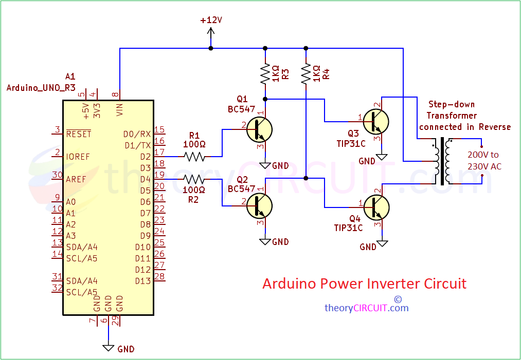
Arduino Power Inverter Circuit Diagram
Components Required
- Arduino Uno board
- 12-0-12V AC Step Down Transformer 1 Amps
- Transistor TIP31C (NPN) = 2
- Transistor BC547 (NPN) = 2
- Resistor 100Ω = 2
- Resistor 1KΩ = 2
- DC Power supply source 12V
- Connecting wires
Construction & Working

Working Video
Inverter circuit construction & Working Details
This circuit is designed to get 200V AC to 230V AC output supply from minimum 12V DC supply. Arduino digital pin 2 and 4 are programmed to make HIGH and LOW timing pulse for every 150 micro seconds in loop mode. Then this timing pulse connected with the Transistor Q1, Q2 base terminals and these two transistors acts as Switch and produce high voltage pulse enough to drive TIP31C Transistors. Collector terminal of two TIP31C are connected with the transformer secondary to induce magnetic flux by using +12V input to the center tap terminal.
For each High and Low timing pulse from the Arduino these two TIP31C transistors gets ON and OFF then allows supply (+12V) through center tap of secondary winding to reach GND and make magnetic flux, this fast changing magnetic flux is high enough to induce voltage at the primary winding. Hence we receive High AC supply at the primary terminals. For to know more about Step-down Transformer read here.
Simple Arduino Power Inverter Circuit Code
/*
  Arduino Power Inverter Circuit

  Made with Power transistor TIP31C and General purpose Transistor BC547

  It can turn 12V DC input to 230V AC output
 Link: https://theorycircuit.com/power-circuits/Simple-Arduino-Power-Inverter-Circuit/
 by theoryCIRCUIT

*/

void setup() {
  // initialize digital pin 2 and 4 as an output.
  pinMode(2, OUTPUT);
   pinMode(4, OUTPUT);
}

// Making Switching Pulse to drive Transformer Secodary through Transistors
void loop() {
  digitalWrite(2, HIGH);
  digitalWrite(4, LOW);
  delayMicroseconds(150);   // delay in micro seconds
  digitalWrite(4, HIGH);
  digitalWrite(2, LOW);
  delayMicroseconds(150);  // delay in micro seconds
}
Adjust the delayMicroseconds(150); Number to get different level of output AC Voltage.