
Last Updated on May 2, 2024
Inverter Circuits are used to convert low voltage DC supply into high voltage AC supply output. By using this circuit we can drive AC Electrical appliances like bulb or fan during power supply interrupt or failure situations. For to achieve that we need to have 12V Rechargeable battery, to give DC power supply input. This simple IC 555 Inverter Circuit designed with minimum components to reduce cost of designing and complexity.
Here we are going to use Induced magnetic flux in the Secondary winding of transformer to induce High voltage in the Primary winding of transformer. We know that step-down transformer will have High number of windings in primary and low number of windings in secondary. So we are going to invert this transformer like secondary winding as Input to make magnetic flux with the help of Input (+12V) DC supply and switching pulse then Primary winding as output to Induce high voltage with the help of electromagnetic Induction. To know more about step-down Transformer read here.
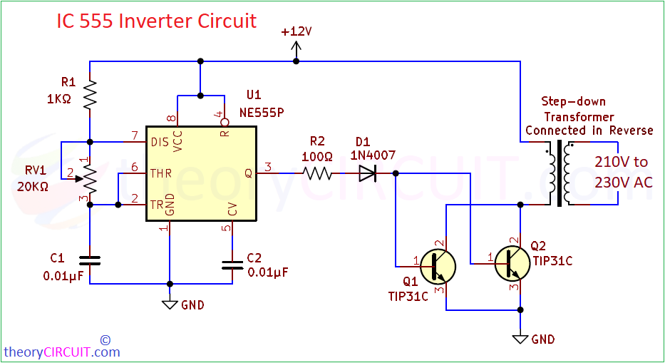
IC 555 Inverter Circuit Diagram
This simple inverter circuit involves in handling of high voltage AC supply at the output so handle with extreme care.
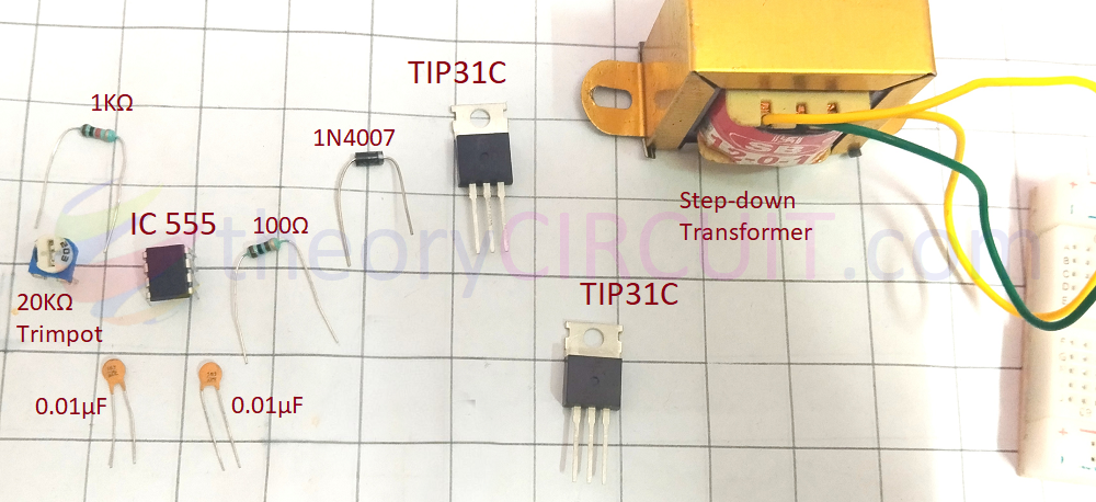
Components Required for Simple Inverter Circuit
- Timer IC NE555P = 1
- Step down Transformer 12VAC / 1 Amps
- Power Transistor TIP31C (NPN) = 2
- Diode 1N4007 = 1
- Variable Resistor 20KΩ = 1
- Resistor 1KΩ, 100Ω = each one
- 0.01μF Ceramic disc Capacitor = 2
- connecting wires
Working Video
Construction & Working
To produce varying (alternating) magnetic flux in the coil, we need to make the supply through coil ON and OFF at higher frequency. To do that we use power Transistor TIP31C as a switch and Timer IC 555 as a High frequency pulse oscillating device.
Here the timer IC 555 is configured in Astable Multivibrator mode and produce High frequency pulse output as per the timing Resistor R1, RV1 and timing capacitor C1. Use 555 Astable Multivibrator Calculator for frequency output calculations with different value of timing components. This inverter circuit produce pulse frequency from (3 KHz to 8 KHz) for 20KΩ to 10KΩ range RV1 (Variable Resistor Value).
When the power supply applied to this circuit, in IC 555 section, capacitor C1 charges through series combination Resistors R1 and RV1 towards Vcc. Once the voltage across the C1 capacitor reaches 2/3 Vcc then upper comparator (Threshold) makes internal flip flop of 555 Set and setting the output to HIGH in pin 3. During this time capacitor C1 discharge through RV1 (Discharge pin). When C1 capacitor charge reaches 1/3 Vcc then the lower comparator Resets the internal flip flop of 555 and setting the output to LOW in pin 3. Again Capacitor C1 starts charging and this cycle repeats to produce HIGH, LOW timing pulse. This pulse output from pin 3 is connected to the parallel transistors TIP31C setup through reverse protection diode 1N4007. This two TIP31C transistors acts as switch with high current capability and makes secondary transformer coil ON & OFF with respect to the base input pulse frequency.
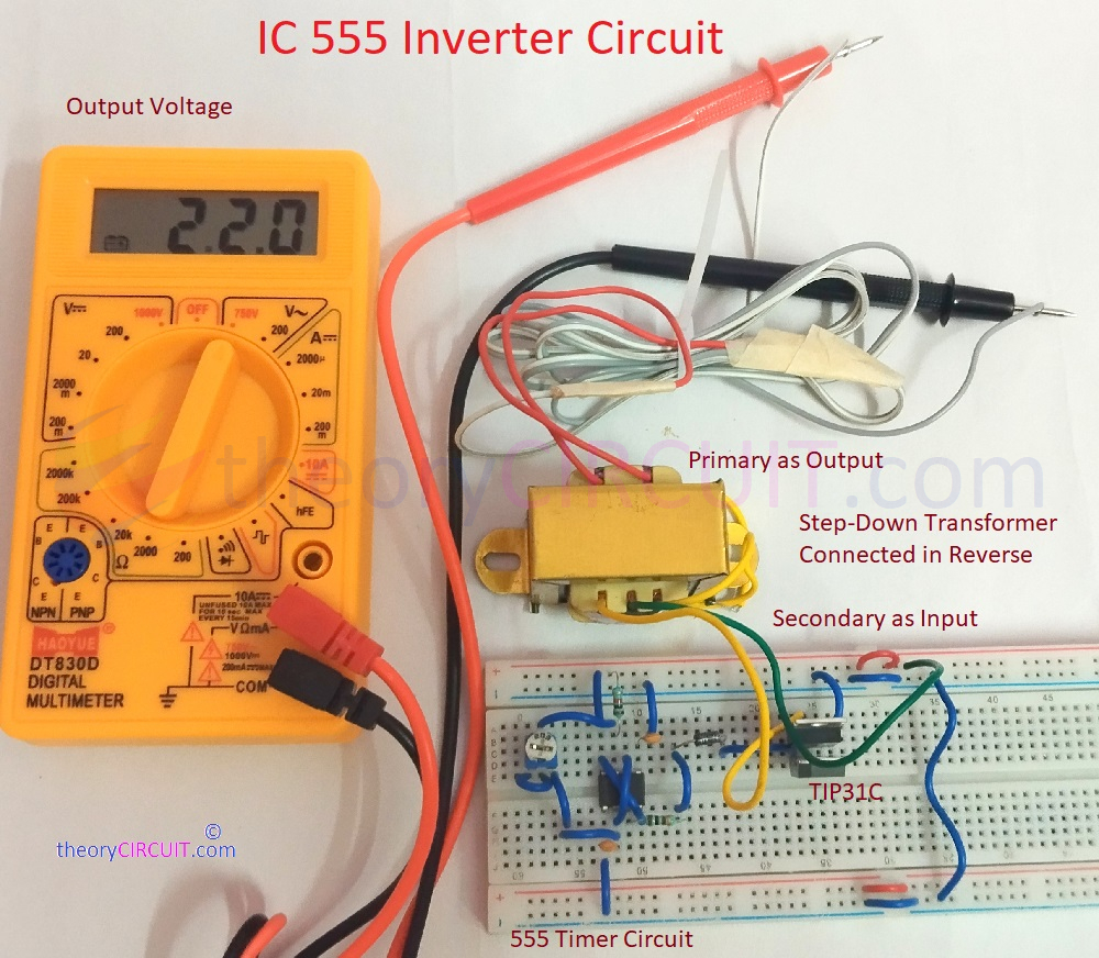
Due to High varying magnetic flux, primary coil gets electro magnetic Induction and produce High AC voltage from 210 Volts to 230 Volts and it can be varied by changing VR1 value. Keep in mind that the frequency output from the 555 should be between 3 KHz to 8 KHz, always check the output voltage from the primary side using digital multimeter before connecting AC load. This circuit gives High Voltage AC output so handle with extreme care to avoid lethal electric shock.