Last Updated on March 16, 2024
Simple two transistor based lie detector circuit is just a fun electronic circuit, some times works effectively and finds liar among your friends. Just try it as a fun hobby project.
This lie detector circuit works based on the skin resistance variations, consider a person when he lie during the conversation his anexiety level will rise and it makes him to sweat so his hands & finger becomes moisture by using this lie detector circuit we can detect those moments by the way of conductivity and resistance variation then LEDs glows depends on the moisture & conductivity of the skin.
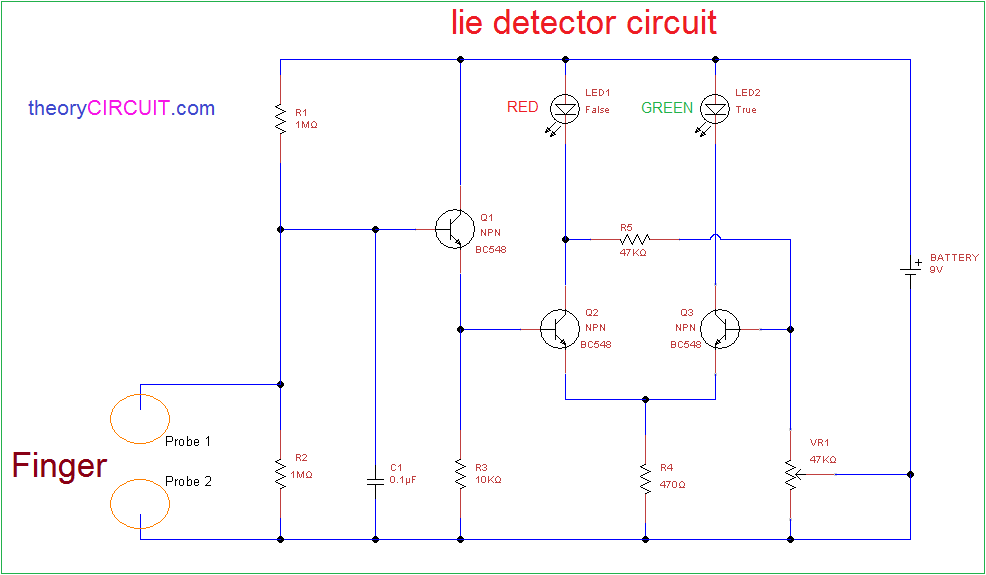
Circuit diagram
Components
- Transistor BC548 (NPN) x 3
- LED (Green = 1, Red = 1)
- Trimpot (Variable Resistor VR1) 47KΩ = 1
- Resistors (1MΩ = 2, 10KΩ = 1, 47KΩ = 1, 470Ω = 1)
- Capacitor 0.1μF = 1
- Battery 9V = 1
- Connecting wires as required
- tiny Copper plate for fingers (you can use copper wire)
Construction & Working
This simple circuit can be easily built on bread board or can be soldered in a common dot board. Q1 transistor base terminal takes the input from finger, it is responsible for to detect the resistance changes in finger, Red LED connected to the collector terminal of Q2 transistor this LED represents the detection of lie. Green LED is connected with Q3 transistor this LED represents detection of true.
Variable resistor VR1 decides the sensitivity level of circuit. When the finger skin resistance is high the Q1 don’t get any bias and it becomes turn OFF then Q2 also don’t get any bias then Q3 only gets bias through Q2 collector terminal and Green LED glows to represent true.
If the finger skin is wet and then resistance on skin becomes very low hence the Q1 gets bias then it becomes turn ON due that Q2 also gets turn ON because it’s base terminal connected with Q1 transistor emitter then Red LED starts glow and indicates the lie.
Note:-
It is a hobby electronic circuit, and not recommended for professional use.

