Last Updated on September 30, 2024
Here ESP32 dev board used to read Analog Input in Arduino IDE, the ESP32 Microcontroller with WiFi and Bluetooth connectivity made easy to build IoT device and connected Embedded devices. If you are look at any Embedded System there will be three stage like Input, Processing and Output. Here the Input obtained from sensors and most sensor gives analog output. This ESP32 microcontroller have two built in ADC (Analog to Digital Converter),
- ADC1 has 8 channels (GPIOs 32 to 39).
- ADC2 has 10 channels (GPIOs 0, 2, 4, 12 to 15, and 25 to 27).
Here ADC Resolution can be configured up to 12 bits so the microcontroller ADC block providing 4096 different values.
One of the essential feature of ESP32 is its ability to read analog inputs, which allows you to measure varying signals such as those from sensors or variable Resistor.
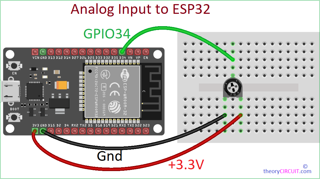
Wiring Diagram
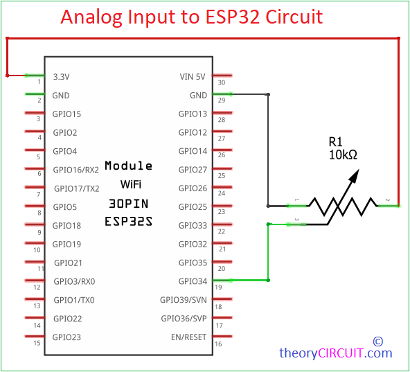
Circuit
Components Required
- ESP32 Development Board
- Potentiometer (or any other analog sensor)
- Breadboard
- Jumper Wires
- USB Cable (USB A Type to Micro USB B Type)
Here we are going to make experiment to read analog input using ESP32 board and a Variable Resistor (Trimpot) as our input device. We have used Arduino IDE for coding and testing. If you are new to ESP32 board Read Here to get started with ESP32 and Arduino IDE.
Analog Input
We know that ESP32 microcontroller have multiple Analog to Digital Converter (ADC) Pins, and these are reads Analog voltages between 0 and 3.3V. The internal ADC block converts the input analog voltage to a Digital Value, in a range of 0 to 4095 for 12 – bit precision and you can change it to 10 – bit precision, so you can get 0 to 1023 digital values.
Here the Voltage across the Variable Resistor (trimpot) changes as it sresistance is adjusted, by connecting it to the ESP32 we can read varying voltage using internal ADC, So that we can code to control output based on the input voltage.
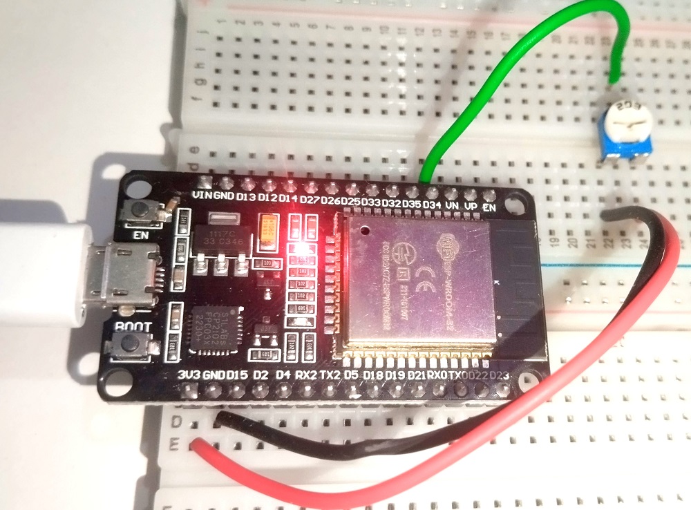
Construction & Working
This experiment use simple trimpot as input device, you can use any variable Resistor or sensor that gives maximum 3.3V output. If you are using 5 Volt output sensor then you need to convert it from 5V to 3.3V logic before connecting it to ESP32 pin.
Connect the first pin of trimpot to the Ground (GND) on the ESP32 (use common Gnd for sensors), then connect VCC (3.3V) to the third pin and then connect middle pin (wiper pin / output pin) to the ESP32’s Analog pin (ADC pin), here we used GPIO34 (ADC 1 Channel 6), you can use any one ADC pin.
Arduino Code
Before start to code ESP32 board make sure that you have Installed ESP32 board in you Arduino IDE.
// Define the analog input pin
const int analogPin = 34; // GPIO 34 (Analog Pin)
// Variable to store the value from the analog pin
int analogValue = 0;
void setup() {
// Start the serial communication
Serial.begin(115200);
}
void loop() {
// Read the analog value from the trimpot (0 to 4095 for 12-bit resolution)
analogValue = analogRead(analogPin);
// Map the analog value to a voltage range (0V to 3.3V)
float voltage = (analogValue / 4095.0) * 3.3;
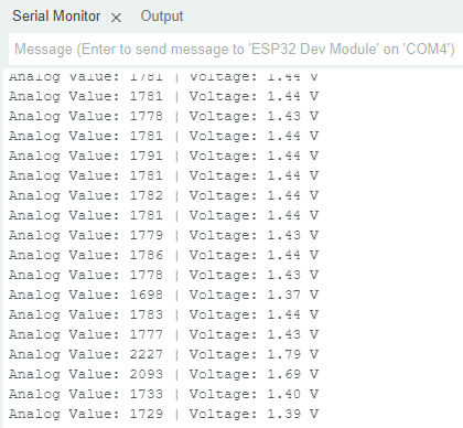
// Print the analog value and corresponding voltage to the Serial Monitor
Serial.print("Analog Value: ");
Serial.print(analogValue);
Serial.print(" | Voltage: ");
Serial.print(voltage);
Serial.println(" V");
// Small delay to make the output readable
delay(500);
}
Serial Monitor Output