
Last Updated on October 8, 2025
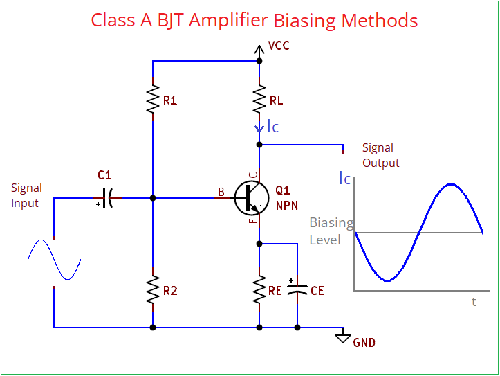
When I first started experimenting with transistor amplifiers, the most confusing part was not the gain calculations but how to bias the transistor correctly. If the biasing is wrong then the amplifier either clips the signal or distorts heavily sometimes the transistor doesn’t even turn ON. That is why understanding biasing methods is very important before building a class A Amplifier. Here I have taken a simple BJT transistor (NPN), now lets see the common biasing methods used to make it as Class A amplifier and the operation.
What is Biasing in BJT?
In simple words biasing means providing the correct DC supply (operating point – Q point) to the transistor. So that it stays in the Active region for class A amplifier main transistor should remain conducting for the entire input signal cycle 360°, because when,
Bias is too low then Transistor cuts OFF.
Bias is too High then Transistor saturates.
Hence the biasing is important for transistor and biasing is all about fixing the base current (IB) and Collector Voltage (VC) so that the transistor amplifiers the AC signal without distortion.
Basic thing in Class A Amplifier
- Transistor Configured in Common Emitter Configuration.
- Operating point (Q-Point) placed at the center of load line.
- Current flow occurs for the entire input cycle.
- Gives very low efficiency but the linearity is excellent.
Biasing Methods for Class A BJT Amplifier
- Fixed Bias (or) Base Bias
- Collector Feedback bias
- Emitter Feedback Bias
- Voltage Divider bias
We know that silicon transistor requires 0.7V at the base terminal with respect to emitter for to turn ON, when i turns ON then the collector to emitter current flow starts, which may drop up to 0.5V between collector to emitter. Here collector current equals to the base current multiplied with the current gain of transistor.
hFE = DC current gain
β = Amplification Capability in AC
hFE = IC / IB
β = hfe = ΔIC / ΔIB
For PNP transistor it works in reverse, by applying base voltage we can turn OFF transistor.
Fixed Bias (or) Base Bias
This is the Simplest biasing method here a Resistor is connected from the supply voltage (Vcc) to the base terminal. Resistor RB connected between Vcc and base, RC connected between Vcc and Collector, Emitter usually grounded. Input and Output coupled with capacitor to block DC.
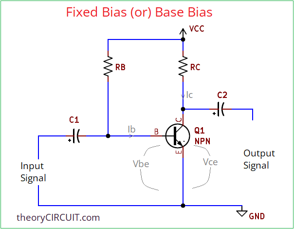
For this bias we need to calculate Vcc and then base emitter voltage (for silicon based transistor it will be 0.7V and for germanium based transistor it will be 0.3V) then IB (base current) and IC (collector current).
RB = (Vcc-Vbe) / IB
here Vbe is 0.7V and IB = IC / β.
RC = Vcc / (2*IC) for midpoint biasing.
This circuit provides high voltage gain. It is suitable for pre amplification.
Collector Feedback Bias
It can be named as collector to base bias, In this bias the base Resistor (RB) connected from collector to base terminal and it provides Negative feedback. Here the collector voltage VC influences the base bias. If collector current IC increases then collector voltage (VC) drops, then it will reduce IB and then stabilizes IC. So this bias self adjust. Here emitter is grounded and RC is connected to Vcc.
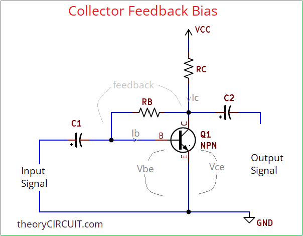
VB = VC * (β/(β+1))
Emitter Feedback Bias
Here an emitter Resistor RE is connected between emitter terminal to Ground. This makes degenerative feedback. RB connected from collector terminal to base like in collector feedback bias. If the IC increases then the Voltage drop across RE rises and reduce VBE, IB levels.
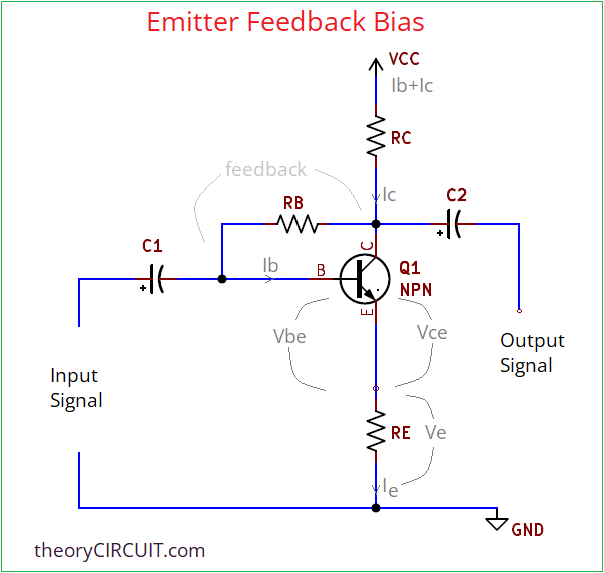
RB = (Vcc-Vbe-(Ie*RE))/Ib
Voltage Divider Bias
Voltage divider bias is the most stable and most used biasing method for NPN transistors in the signal amplification. Here two Resistors R1, R2 form a divider from Vcc to GND and sets the base voltage VB. Emitter Resistor RE provides stability and collector terminal is connected with VCC through RC.
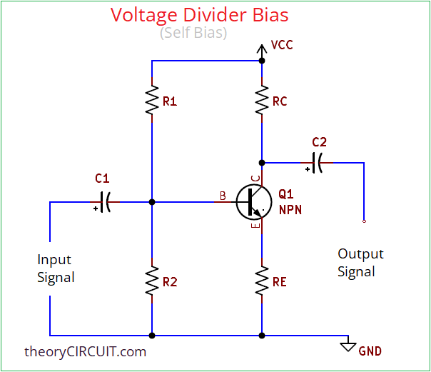
VB = VCC * (R2/(R1+R2))
VE = VB-VBE
IC = VE/RE
Here RE drops 0.5 to 2V at the IC and Vbe = Vb – (Ie * Re). Here R2 should be at least 10 times greater that RE. Connecting decoupling capacitor at the Emitter and I/O is recommended to increase the gain. Depends on the application we can choose any biasing methods.