
Last Updated on November 4, 2025
If you want to add color and light effects in yor small projects with limited space and power then you can try Interfacing RGB LED with ATtiny85 microcontroller. Because Attiny85 is a tiny yet powerful microcontroller that can easily drive an RGB LED and bring custom Efects using two pwm pins. Here we will see how to Interface a common cathode RGB LED with Attiny85 and control its color using simple code. It is a beginer friendly Project and requires only a few components. You can build and test it on a breadboard in just a few times minutes.
Types of RGB LED
An RGB LED is basically three LEDs (Red, Green and Blue) packed into one package. By controlling the intensity of these three LEDs we can make a wide range of colors. There are two main types of RGB LEDs,
- Common Cathode (CC) – All Cathodes are connected together inside the package.
- Common Anode (CA) – All Anodes are connected together inside the package.
Here we use Common Cathode RGB LED.
Circuit Wiring
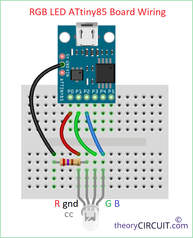
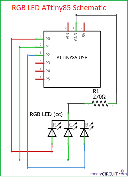
| ATtiny85 | RGB LED (CC) |
| GND | GND (Through 270Ω) |
| PB0 | Red pin |
| PB1 | Green pin |
| PB2 | Blue pin |
Use Digital multimeter in diode mode to easily identify the common pin and color of RGB LED pin.
Components Used
- ATtiny85 microcontroller board from Digispark or with Micronucleus bootloader.
- Common Cathode RGB LED
- Resistor 270Ω
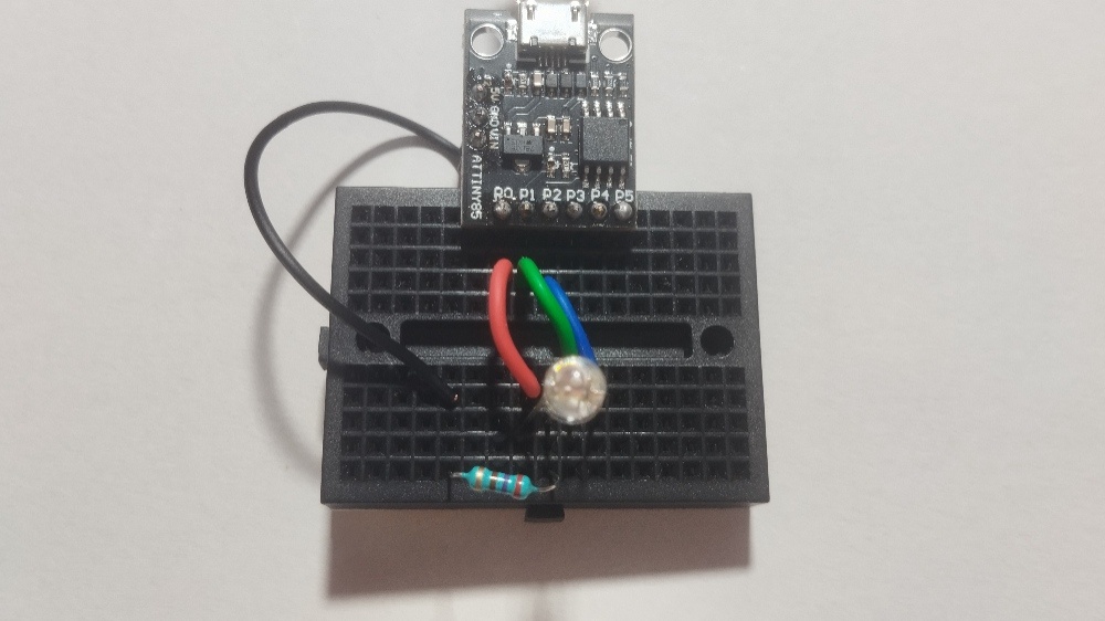
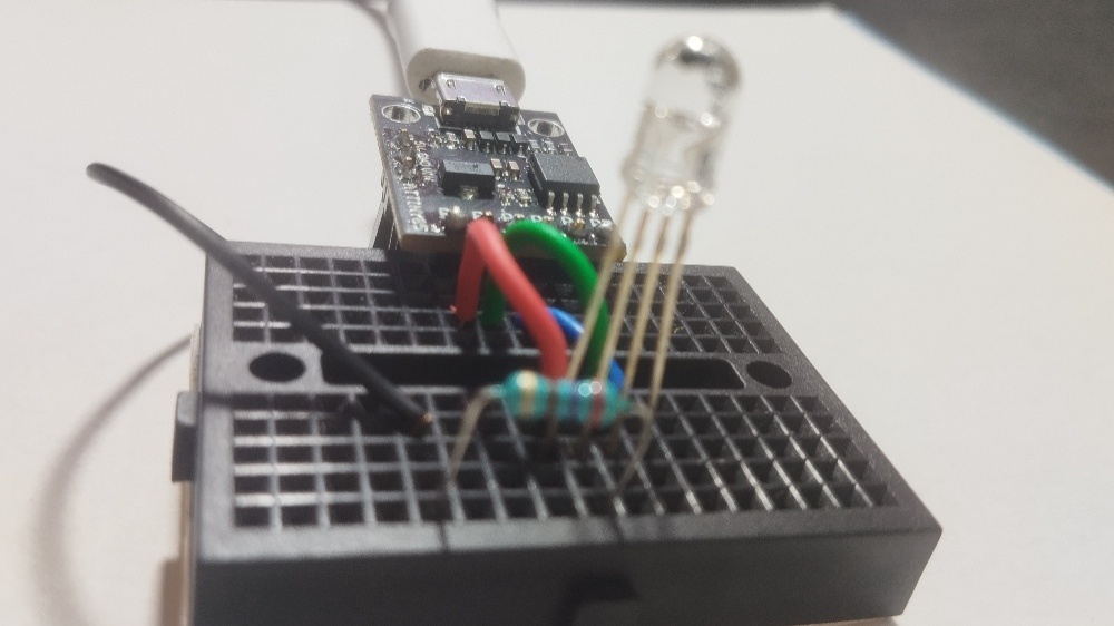
- Breadboard and Connecting wires
Operation and Code
Here we driving each color pin of RGB LED using one GPIO pin from ATtiny85 and common pin is grounded through current limiting Resistor. By writing digital HIGH or LOW to PB0, PB1 and PB2, we can turn ON or OFF each color channel. Combining them gives different color output. Like Red + Green = Yellow, Green + Blue = Cyan, Red + Blue = Magenta and Red + Green + Blue = white. Make your own color by mixing these primary colors.
Arduino Code for ATtiny85 RGB LED
If you are new to begin with ATtiny85 then read here. Make sure that Arduino IDE have ATtiny board and core files Installed and ATtiny85 have Micronucleus bootloader, Digispark and development boards will have default bootloader on ATtiny85 microcontroller.
// Interfacing Common Cathode RGB LED with ATtiny85
// Pin connections: R -> PB0, G -> PB1, B -> PB2

#define RED   0   // Pin 5
#define GREEN 1   // Pin 6
#define BLUE  2   // Pin 7

void setup() {
  pinMode(RED, OUTPUT);
  pinMode(GREEN, OUTPUT);
  pinMode(BLUE, OUTPUT);
}

void loop() {
  setColor(1, 0, 0); // Red
  delay(500);
  setColor(0, 1, 0); // Green
  delay(500);
  setColor(0, 0, 1); // Blue
  delay(500);
  setColor(1, 1, 0); // Yellow
  delay(500);
  setColor(0, 1, 1); // Cyan
  delay(500);
  setColor(1, 0, 1); // Magenta
  delay(500);
  setColor(1, 1, 1); // White
  delay(500);
  setColor(0, 0, 0); // OFF
  delay(500);
}

void setColor(bool r, bool g, bool b) {
  digitalWrite(RED, r);
  digitalWrite(GREEN, g);
  digitalWrite(BLUE, b);
}
Here setColor() function allows us to easily switch to ON or OFF each color by passing Boolean value, and logic HIGH=1 turns ON the color and LOW=0 turns OFF. You can add PWM control using analogWrite() on PB0, PB1 pins to make fading effects.