Last Updated on March 16, 2024
AC Lamp Power Control Circuit using SCR, the AC Lamp Power Control Circuit is designed to regulate the power supplied to lamps, allowing for brightness control and energy conservation. It operates on alternating current (AC) power, the standard electrical supply in our homes and businesses. By utilizing electronic components such as resistors, capacitors, and semiconductor devices, this circuitry achieves precise control over the luminosity of lamps.
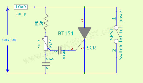
The ability to control the brightness of lamps is essential for creating ambiance, conserving energy, and ensuring longevity of lighting devices. One effective way to achieve this control is by utilizing the SCR BT151 (Silicon Controlled Rectifier) in an AC Lamp Power Control Circuit. Switch across the circuit can be used to provide full power supply to the AC Lamp and bypass the SCR Power Control Circuit.
Circuit Diagram
Note: This circuit is referred for only Professionals in handling Electric supply, This circuit involves in handling of High voltage AC supply and Might Lethal, Handle with Extreme Care.
Components List
| S.No | Name | Quantity |
| 1. | SCR BT151 series C | 1 |
| 2. | Capacitor 0.1uF | 2 |
| 3. | Resistor 3K Variable Resistor 100K | 1 1 |
| 3. | SPST Switch(230V) | 1 |
Circuit Construction & Working
The SCR BT151 is a versatile semiconductor device that acts as an excellent switch for controlling AC power. Its ability to handle high voltages and currents makes it an ideal choice for applications where precise power control is required.
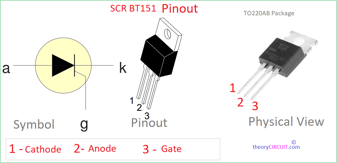
This circuit can operate from 120V AC to 240V AC, Connect target load (lamp) in series with the power control circuit. Variable Resistor RVAR controls the flow of Gate voltage and we know the SCR conducts from Anode to Cathode when there is enough gate supply. By offering low Resistance path to power supply we can reduce the supply level to the lamp. SPST switch is for bypassing the control circuit.