
Last Updated on March 16, 2024
Simple High Current Low Voltage Regulator Circuit designed by using IC MIC29302WT from Microchip, Some Electronic Circuit Design or Device requires Low voltage with High Current Input supply and prototyping different circuit also requires Constant High Current bias, Here simple, cost effective and easy to construct circuit is designed with few easily available elements.
The MIC29302WT is high current, high accuracy, low dropout voltage regulator. this regulator feature 350mV to 425 mV (full load) typical dropout voltages and very low ground current. Designed for high Current loads, this device also find applications in lower current, extremely low dropout-critical systems, where their tiny dropout voltage and ground current values are important attributes.
As per the Microchip claim This IC Gives Accurate 1% Guaranteed Tolerance, Extremely Fast Transient Response, Reverse-Battery and “Load Dump” Protection and Zero Current Shutdown Mode for 5-Pin Versions ICs. This IC series comes in Fixed Voltage and Adjustable Versions.
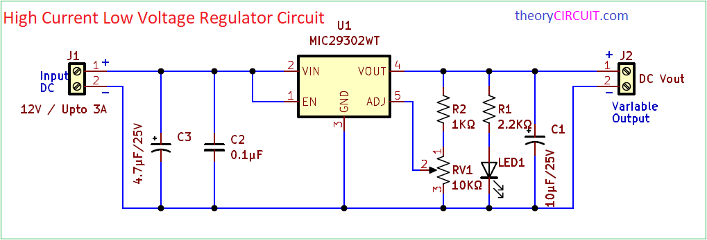
Circuit Diagram
Components Required (BOM for PCB)
| 1 | C1 | 10μF/25V | CP_Radial_D5.0mm_P2.50mm | 1 | ||
| 2 | C2 | 0.1μF | C_Disc_D3.4mm_W2.1mm_P2.50mm | 1 | ||
| 3 | C3 | 4.7μF/25V | CP_Radial_D5.0mm_P2.50mm | 1 | ||
| 4 | R1 | 2.2KΩ | R_Axial_DIN0207_L6.3mm_D2.5mm_P10.16mm_Horizontal | 1 | ||
| 5 | R2 | 1KΩ | R_Axial_DIN0207_L6.3mm_D2.5mm_P10.16mm_Horizontal | 1 | ||
| 6 | U1 | MIC29302WT | TO-220-5_P3.4×3.7mm_StaggerEven_Lead3.8mm_Vertical | 1 | ||
| 7 | LED1 | LED | LED_D5.0mm | 1 | ||
| 8 | RV1 | 10KΩ | Potentiometer_Alps_RK097_Single_Horizontal | 1 | ||
| 9 | J1 | 12V / Upto 3A | TerminalBlock_bornier-2_P5.08mm | 1 | ||
| 10 | J2 | DC Vout | TerminalBlock_bornier-2_P5.08mm | 1 |
Construction & Working
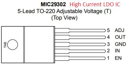
| No, Pin Name | Pin Description |
| 1, EN | CMOS compatible control input. Logic-high = enable, logic-low = shutdown. |
| 2, IN | Unregulated DC Supply Input Pin |
| 3, GND | Common Ground Pin for both input and output |
| 4, OUT | Regulated Output DC Supply Pin |
| 5, ADJ | Adjustable regulator feedback input that connects to the resistor voltage divider that is placed from OUTPUT to GND in order to set the output voltage. |
In this Circuit unregulated 12V DC Supply is applied to the Input pin of MIC29302 after the bias filter capacitors C3 and C2. Here both input DC and Output DC have common Ground. To enable the Regulator IC EN pin is kept in Logic High state that is connected with the input bias positive line. For ADJ input there is a Voltage divider setup implement by using Resistors R2 and RV1 by varying the potentiometer RV1 We can adjust the output voltage.
Vout = 1.25 (R2/RV1 + 1) – Here the output formula is rewritten as per the Designed circuit. Refer Datasheet for more calculations.
An LED is connected between output lines to indicate the presence of Vout and C1 Electrolytic capacitor performs output DC Filtering. This circuit can used as a Adjustable DC Voltage Regulator. Some fixed Version of ICs also available in this series from microchip. Operation of this LDO depends on three internal circuitry, those are pass element, error amplifier, and reference voltage source. The MIC29302 employs a feedback control mechanism to compare the output voltage to a reference voltage. If there is any deviation from the desired output voltage, the regulator adjusts its internal components to bring the output voltage back to the set point.
This Circuit can be constructed in common PCB (Dot PCB board). For Professional prototype and testing use the PCB Gerber files.
Printed Circuit Board
High Current Low Voltage Regulator Circuit PCB Gerber Files.
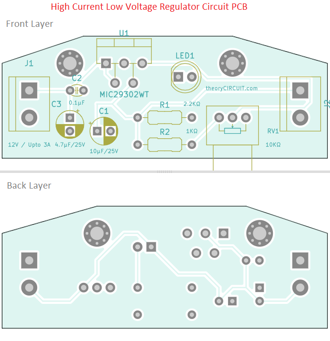
Interactive Board Viewer

