
Last Updated on March 16, 2024
USB Li-ion Battery Charger Circuit designed by using LP2951 (Adjustable Micropower Voltage Regulators with Shutdown) from Texas Instruments. It has wide input range up to 30V and gives good voltage regulation with low Quiescent Current. IC LP2950 gives fixed output voltages as 5 V, 3.3 V, and 3 V depending on the version. LP2950 comes in TO-92 package with only three pins.
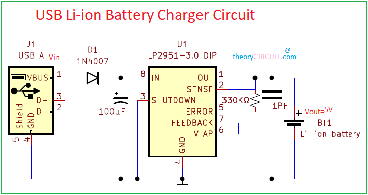
The IC LP2951 is an adjustable micropower voltage regulator suitable for use in battery-powered systems. However, the 8-pin LP2951 can output either a fixed or adjustable output from the same device. By tying the OUTPUT and SENSE pin together, and the FEEDBACK and VTAP pin together.
Circuit Diagram
BOM
| S no | Designator | Value | Quantity |
| 1 | IC | LP2951 | 1 |
| 2 | USB-A | 1 | |
| 3 | Diode | 1N4007 | 1 |
| 4 | Resistor | 330KΩ | 1 |
| 5 | capacitor | 100μF | 1 |
| Capacitor | 1PF | 1 | |
| 6 | Battery(Li-ion) | 1 |
Construction and Working
In the given circuit the IC 2951 became the main active component which has been specifically chosen because it is capable of delivering an output voltage thats very stable over temperature. Initially when the particular discharge cell has a voltage level that below the 4.2V the IC generates maximum current to the cell which is around 160mA.
A unique feature of the LP2951 device is its ability to output either a fixed voltage or an adjustable voltage, depending on the external pin connection. To output the internally programmed fixed voltage, tie the SENSE pin to the OUTPUT pin and the FEEDBACK pin to the VTAP pin. These device can be placed in the SHUTDOWN pin. Return the logic level low to restore operation or tie SHUTDOWN to the ground if the feature is not being used.
Here the USB-A is an input source the Vbus pin is directly connected to diode 1N4007 for the use of reverse protection. And the LP2951 device is a significant impedance between the ac filter capacitor connected to the Vin pin. Tie pin 2 and pin 5 through the 330KΩ resistor. Once the terminal voltage of the Li-ion cell reaches the 4.2V mark, the IC LP2951 instantly inhibits the current so that the battery can longer exceed the 4.2V level. The big value resistor included in the circuit ensures the OFF current drain of the battery to below 2mA. The capacitor stabilizes the circuit from unwanted noises created at the high-impedance feedback node.