
Last Updated on March 16, 2024
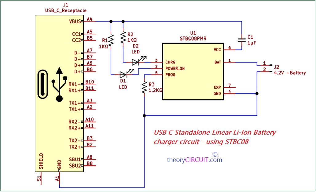
Simple and easy to construct USB C Standalone Linear Li-Ion Battery charger circuit designed by using IC STBC08 from STMicroelectronics. As we know a standalone linear Li-Ion battery charger circuit refers to an electronic circuit designed to charge lithium-ion (Li-Ion) batteries using a linear charging method without the need for additional control circuitry or a microcontroller. It is a self-contained charging solution that can be used independently without complex external circuitry.
This circuit includes essential components such as a charging IC STBC08, current regulation circuitry, voltage regulation circuitry, and necessary safety features like overvoltage protection, overcurrent protection, and temperature monitoring. The charging IC STBC08 is responsible for controlling the charging process, monitoring battery voltage and current, and ensuring safe and efficient charging. This circuit provides up to 800mA charging current.
A standalone linear Li-Ion battery charger circuit with USB C Receptacle can be used in various applications such as portable electronics, power banks, battery-powered devices, and other battery-operated systems. It offers a convenient and straightforward solution for charging Li-Ion batteries without the need for complex external control or monitoring systems.
Circuit Diagram
Components Required
| 1 | C1 | 1µF | C_0805_2012Metric | 1 | ||
| 2 | R1, R2 | 1KΩ | R_0805_2012Metric | 2 | ||
| 3 | R3 | 1.2KΩ | R_0805_2012Metric | 1 | ||
| 4 | D1, D2 | LED | LED_0805_2012Metric | 2 | ||
| 5 | U1 | STBC08PMR | DFN-6-1EP_3x3mm_P1mm_EP1.5×2.4mm | 1 | ||
| 6 | J2 | 4.2V -Battery | JST_EH_B2B-EH-A_1x02_P2.50mm_Vertical | 1 | ||
| 7 | J1 | USB_C_Receptacle | USB_C_Receptacle_Amphenol_12401548E4-2A | 1 |
Construction & Working
IC STBC08
The IC STBC08 is a constant current/constant voltage charger for single-cell Li-Ion batteries. Neither external sense resistor nor blocking diode are required. The STBC08 is designed to work within USB power specifications. An internal block regulates the current when the junction temperature increases, to protect the device when it operates in high power or high ambient temperature conditions. The charge voltage is fixed at 4.2 V, and current limitation can be programmed using a single resistor connected between PROG pin and GND. It comes in DFN6 (3 x 3 mm) package. Refer datasheet for more information.
To construct this circuit we need a USB C Receptacle, IC STBC08, Discrete components as mentioned in the Components Required table and finally PCB. A charge cycle begins when the voltage at the VCC pin rises above UVLO threshold level, RPROG program resistor of 1% is connected between PROG pin and GND pin and when a battery is connected to the charger output. If the battery voltage is below 2.9 V, the charger enters trickle charge mode. In this condition, the device supplies 1/10th of the programmed charge current to keep the battery voltage in a safe level otherwise the life of a battery reduces. If BAT pin voltage is higher than 2.9 V the charger goes to constant current mode. When BAT pin voltage is close to the final float voltage (4.2 V) the device goes to constant voltage mode and the charge current begins decreasing. The charge cycle is over when the current drops 1/10th of the programmed value. Refer Datasheet for more information.
Printed Circuit Board
USB C Standalone Linear Li-Ion Battery charger circuit Gerber Files.
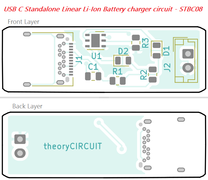
Interactive Board Viewer

