Last Updated on March 16, 2024
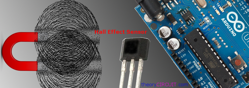
The Hall Effect sensor involves in contact less sensing to count the number of revolutions of a wheel (digital speedometer), Motor speed and position control and more position detection circuits. This sensor made easy to measure accurate position and steps of rotating device.
Hall effect sensor detects Magnetic flux and gives Hall Voltage differences according to the direction and strength of magnetic flux.
What is Hall Effect?
When the conductor plate is applied to the voltage source, Electrons and holes moves towards the opposite polarity charge terminal, When the magnetic flux present near to the conductor the electron and holes experience a force called Lorentz Force. If the magnetic flux absent the charge carriers (Electron & Holes) follows approximately straight path. This is leads to Hall effect in the conductor plate.
Hall Effect Sensor Block diagram
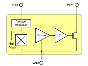 Typical Hall Effect sensor has three important blocks called Hall plate, Voltage Regulator, and Chopper.
The Hall Effect sensor available in two categories they are Linear output sensor and Digital output sensor. Schmitt trigger block is available in digital hall effect sensor, Output signal of linear sensor directly taken from the operational amplifier, it gives amplified Hall voltage from the Hall plate. Schmitt trigger conversion takes place if we use digital output sensor. So it gives ON and OFF states according to the Hall plate output.
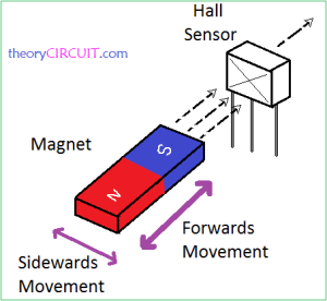
The Hall Effect sensor detects magnetic flux from permanent magnet attached to a moving shaft or device, and also it is sensible to different types of magnet movements such as “Head-on, Side Way, Push-Push or Push-Pull” etc..,
Depends on the Magnet polarity, flux strength and air gap between magnet and Hall effect sensor the output hall voltage gets varied.
Here the illustration given for example operation of hall effect sensor, the magnet is essential for the hall sensor operation, permanent magnet available in different size and forms so we can use according to our needs.
Connecting Hall Effect Sensor to Arduino
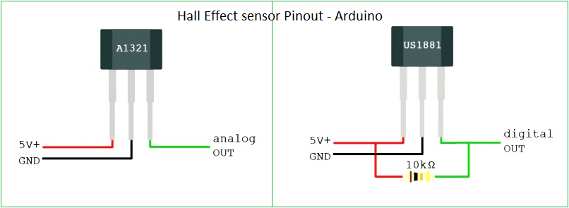
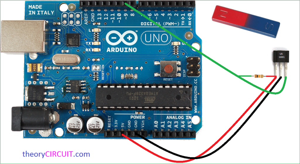
Here two Hall effect sensors Pinout given, The A1321 range sensor gives analog out (linear sensor) and US1881 range sensor gives digital out, both sensors can be easily interfaced with Arduino board, if we use digital hall effect sensor we need to give bias from +5V to the output terminal through 10KΩ resistor.
As shown in the hookup diagram connect the Hall Effect sensor with Arduino board, here we used US1881 digital out hall sensor and permanent bar magnet. This circuit can be used to detect the magnet present and absent and also movement.
Arduino Code
/* Hall Effect sensor as Switch  www.theorycircuit.com */


const int hallPin = 9;     // hall effect sensor out pin
const int ledPin =  13;    // LED pin

int hallState = 0;         // Initial hall sensor status

void setup() {

  pinMode(ledPin, OUTPUT); // LED pin as an output

  pinMode(hallPin, INPUT); // The hall effect sensor pin as an input
}

void loop(){

  hallState = digitalRead(hallPin); // reading the state of the hall effect sensor pin

  if (hallState == LOW) {

    digitalWrite(ledPin, HIGH);  // turn LED on
  }
  else {

    digitalWrite(ledPin, LOW);  // turn LED off
  }
}

Hey, why do you need to use a resistor to get digital signal?
In my opinion, they used to prevent the heating
It is not the overheating, it is to make the signal go really up to (near) the power supply voltage
You don’t need that resistor if you use: pinMode(hallPin, INPUT_PULLUP)
How would we add a Monitor to this installation ?
Would it be possible to meassure the distance from Sensor to Magnet, and display it on the Display somehow?